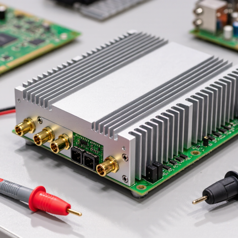
Choosing a Millimeter Wave Power Amplifier starts with the frequency band and the signal it must support. A design for a short-range 60 GHz link may need different output power and bandwidth from one serving a 28 GHz radio. Define the required gain, saturated output power, and linearity before comparing parts. For modulated signals, check error vector magnitude and adjacent-channel performance at the intended output level—not only headline power. Small details matter.
Read the test conditions behind each specification. Gain and efficiency can change with frequency, bias, temperature, and load. Confirm that the amplifier’s usable bandwidth covers the full signal, and review stability, input and output matching, and recommended operating conditions. Heat changes everything. A compact package beside a warm processor may need a careful thermal path, even when its typical efficiency looks adequate. Also consider supply voltage, control features, connector or package transitions, and whether evaluation-board results match your planned layout.
A useful selection process connects the component to the whole radio. Estimate link-budget needs, account for cable and antenna losses, then leave sensible margin without oversizing the amplifier. Compare typical and guaranteed values, and ask suppliers about missing test data or application support. A clean datasheet can still leave gaps; measurement setup and board layout affect real results. Bench testing in the intended configuration is the final check. The right choice is not simply the part with the highest output power. It is the one that meets system targets reliably, within thermal and electrical limits, with performance you can verify.
Choose the amplifier’s frequency band from the radio channel, not a broad “mmWave” label. 3GPP TS 38.104 places NR FR2-1 at 24.25–52.6 GHz, but regional allocations and channel widths vary. That span is not one interchangeable target. A 28 GHz fixed-access link and a 39 GHz backhaul radio need different matching, filtering, and output-stage choices.
Then define the application’s real operating conditions. A rooftop point-to-point link may need stable output power and linearity across a wide modulated signal. An indoor access point may instead prioritize compact size and heat control. Small differences matter. The ITU-R M.2410-0 benchmark sets IMT-2020 peak rates at 20 Gbit/s downlink and 10 Gbit/s uplink; these are system-level targets, not promises from one amplifier. Use them to understand bandwidth demands, not to select output power alone.
Check the exact center frequency, occupied bandwidth, modulation, duty cycle, and temperature range against the amplifier’s test conditions. For outdoor equipment, include cable and antenna losses in the link budget. A datasheet number can look convincing on a bench. It may shift under heat or sustained operation, so validate the chosen band and waveform in the intended enclosure. The first selection is rarely perfect; measurements often reveal an assumption worth revisiting.

Compare common mmWave frequency ranges with their typical applications. Choose an amplifier that covers your full operating band, with suitable output power and linearity for your system.
Note: Frequency allocations and permitted uses vary by region. Confirm the applicable standards and regulations for your deployment before selecting an amplifier.
How to Choose a Millimeter Wave Power Amplifier
Set output power from the link budget, not from the amplifier’s headline rating. Include cable, antenna, enclosure, and temperature losses; a few decibels can decide whether the far edge of a room stays connected. As a reference point, 3GPP TS 38.101-2 specifies a 23 dBm maximum output power for a defined FR2 user-equipment power class. That figure is not a universal amplifier target. Set gain to reach the required power without driving the device into compression, and check performance across the full operating bandwidth.
Linearity matters when signals carry wide, high-order modulations. Review error vector magnitude and adjacent-channel leakage at the intended output level, rather than relying on small-signal specifications. Efficiency also affects the design: a warm chassis in a sealed radio can force power back-off and reduce usable output. Compare power-added efficiency at realistic frequency, bandwidth, and output conditions. There is no perfect trade-off. The 3GPP specification defines system limits; bench tests must confirm that the selected amplifier meets them in your actual thermal and signal conditions.
Tips: Leave output headroom for losses and heat. Ask for measured gain, linearity, and efficiency across your band—not just one favorable test point. Check again at operating temperature.
At millimeter-wave frequencies, amplifier technology affects output power, efficiency, heat, and linearity. GaAs devices often offer a practical balance for high-frequency operation, while GaN can support higher power density but may demand careful thermal design. Silicon-germanium and CMOS can simplify integration with control or signal-processing circuits, though output power and efficiency depend on the process and operating band. No universal winner. Compare measured performance at your actual frequency, not just headline figures.
Integration choices shape the rest of the design. A discrete amplifier allows flexibility in matching and heat sinking, but adds interconnects that can create loss or unwanted reflections. A monolithic microwave integrated circuit reduces those transitions and can make compact modules easier to build. For phased arrays, an integrated front end may combine amplification, phase control, and switching near each antenna element. That matters. Package layout and antenna spacing can still limit performance.
Check gain, bandwidth, output power, and efficiency under realistic drive conditions. Also review thermal resistance, bias requirements, and stability across temperature. A power figure measured at saturation may not reflect performance with a modulated signal and backoff. That assumption deserves a second look. Simulation helps, but board-level measurements often expose grounding or packaging problems that models missed. In practice, a slightly less powerful amplifier with a clear thermal path can be easier to deploy.
| Technology | Typical strengths | Typical trade-offs | Integration potential | Often considered for |
|---|---|---|---|---|
| GaAs pHEMT | Good gain at millimeter-wave frequencies; mature MMIC design options; useful balance of output power, noise, and efficiency. | Generally lower power density and voltage handling than GaN; integration with dense digital circuitry is limited compared with silicon processes. | Well suited to standalone RF MMICs and compact transmit or transceiver modules. | Wireless links, radar, and systems needing a practical balance of gain and output power. |
| GaN HEMT | High breakdown voltage and power density; can support comparatively high output power and better tolerance of high-power operation. | Thermal management, device cost, and power-supply design can be more demanding; integration with digital control is usually less direct. | Commonly implemented as a dedicated power MMIC, often combined with other circuitry in a module. | High-power transmitters, radar, and applications where output power is a priority. |
| SiGe BiCMOS | Combines high-speed bipolar devices with CMOS circuitry; enables substantial integration of RF, control, and some signal-processing functions. | Per-device output power is often more constrained than in dedicated compound-semiconductor power processes; thermal and linearity limits still require attention. | Strong option for integrated transceivers and multi-function silicon chips. | Compact, highly integrated communications and sensing systems. |
| RF CMOS | High integration with digital control and signal-processing blocks; can support cost-effective, scalable designs in suitable production volumes. | Lower device breakdown voltage and limited output power per transistor can make high-power operation challenging; efficiency and heat dissipation need careful design. | Very high potential for single-chip or highly integrated RF solutions. | Mass-market equipment and systems prioritizing integration, size, and production scale. |
| Option | What it includes | Advantages | Design considerations |
|---|---|---|---|
| Bare-die MMIC | An unpackaged monolithic RF amplifier die mounted directly into the system assembly. | Small footprint and flexibility for custom, tightly integrated assemblies. | Requires careful die attach, interconnect, grounding, handling, and thermal design. |
| Packaged amplifier | A single amplifier die in a package with defined RF, power, and ground connections. | Simplifies assembly, handling, and replacement; provides a more standardized interface. | Package parasitics and transitions can affect matching, loss, and performance at millimeter-wave frequencies. |
| Multi-chip RF module | An amplifier combined with supporting RF, bias, filtering, or control components in one assembly. | Can reduce system development effort and optimize interconnects between components. | Thermal paths, module size, internal matching, and test access need to be considered together. |
| Antenna-in-package or antenna-integrated assembly | The amplifier and antenna are co-designed or placed within a shared package or compact assembly. | Can shorten RF paths and support compact phased-array or beamforming designs. | Antenna, package, materials, heat flow, and array layout must be designed as a coupled RF system. |
Selection note: Frequency capability, gain, output power, efficiency, and thermal limits depend on the specific process, circuit design, package, and operating conditions. Compare devices using datasheet specifications measured at the intended frequency, supply voltage, temperature, bandwidth, and linearity requirement.
A millimeter-wave power amplifier can meet its output target and still fail in a warm enclosure. Check thermal resistance, maximum junction temperature, and the conditions used for each rating. A rating measured on a large evaluation board may not hold inside a compact radio. Look closely at the airflow, mounting surface, and duty cycle in your design. Heat has few places to escape.
Reliability needs more than a headline lifetime figure. JEDEC’s JESD22-A110 accelerated humidity test uses 130°C and 85% relative humidity for 96 hours; it is a screening method, not a promise of field life.
Ask whether the amplifier’s package and assembly have relevant qualification data, then compare results with your operating profile. GSMA’s Mobile Economy 2024 report forecasts 5.5 billion 5G connections by 2030, underscoring the growing range of deployment environments.
A rooftop unit, a sheltered indoor radio, and a vehicle installation will not share the same temperature swings or airflow.
Test at the intended frequency, supply voltage, output power, and ambient temperature. Measure case temperature after sustained operation, not just during a brief bench test.
One detail is easy to miss: thermal readings depend on sensor placement. A reading beside the package may understate the hottest point.
A little uncertainty remains until the final enclosure is tested.
Choose a millimeter-wave power amplifier by matching its frequency range, bandwidth, gain, and output power to the complete signal chain. For 5G equipment, 3GPP TS 38.104 defines FR2 operation from 24.25 to 71 GHz. That wide span makes “works at 28 GHz” an incomplete compatibility check. Confirm connector type, impedance, bias requirements, and rated operating temperature. Then compare gain flatness and output power at your actual frequency and modulation bandwidth.
Tips: Request test plots, not just headline figures. Check output power, gain, and error vector magnitude across frequency and temperature. Ask how the unit was calibrated, and whether the test setup matches your intended load and cable losses. Small setup differences matter.
Manufacturer support is part of performance. Ask for the test method, calibration date, and raw data behind key specifications. A data sheet may show saturated output, while your design needs linear output with acceptable distortion. I have seen bench results look convincing until a longer cable or warmer enclosure changed the margin. That is an easy detail to miss. Confirm availability of application engineers, troubleshooting guidance, and replacement or repair timelines before committing. Keep a written record of unanswered questions; vague replies are useful evidence, too.
Registered in England & Wales No. 2786496
Registered office at: 337 Tanworth Lane,
Shirley, Solihull, B90 4DU
Registered for VAT, registration No.
GB 655 1347 38


Location: Nationwide
Not Available for Hire
We can deliver for a cost please ask and send us post code.
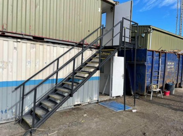
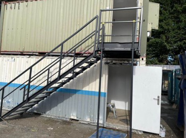
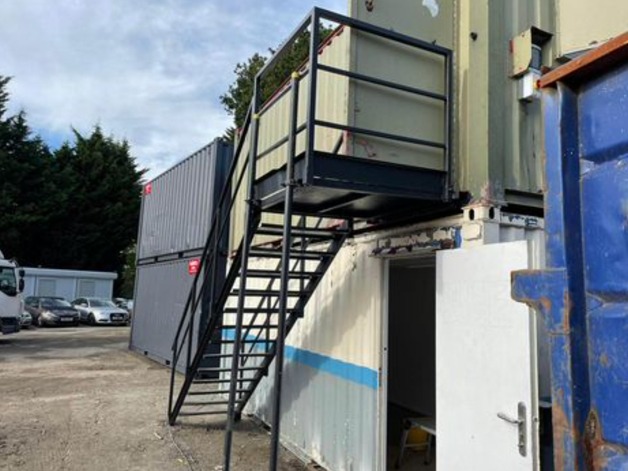
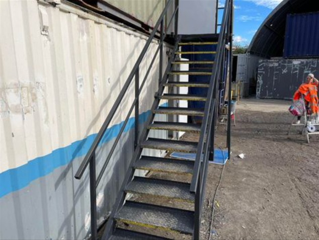
13 tread
14 tread
15 tread


Location: Nationwide
Not Available for Hire
Call for an instant quote!


Location: Nationwide
Not Available for Hire
We can deliver for a cost please ask and send us post code.
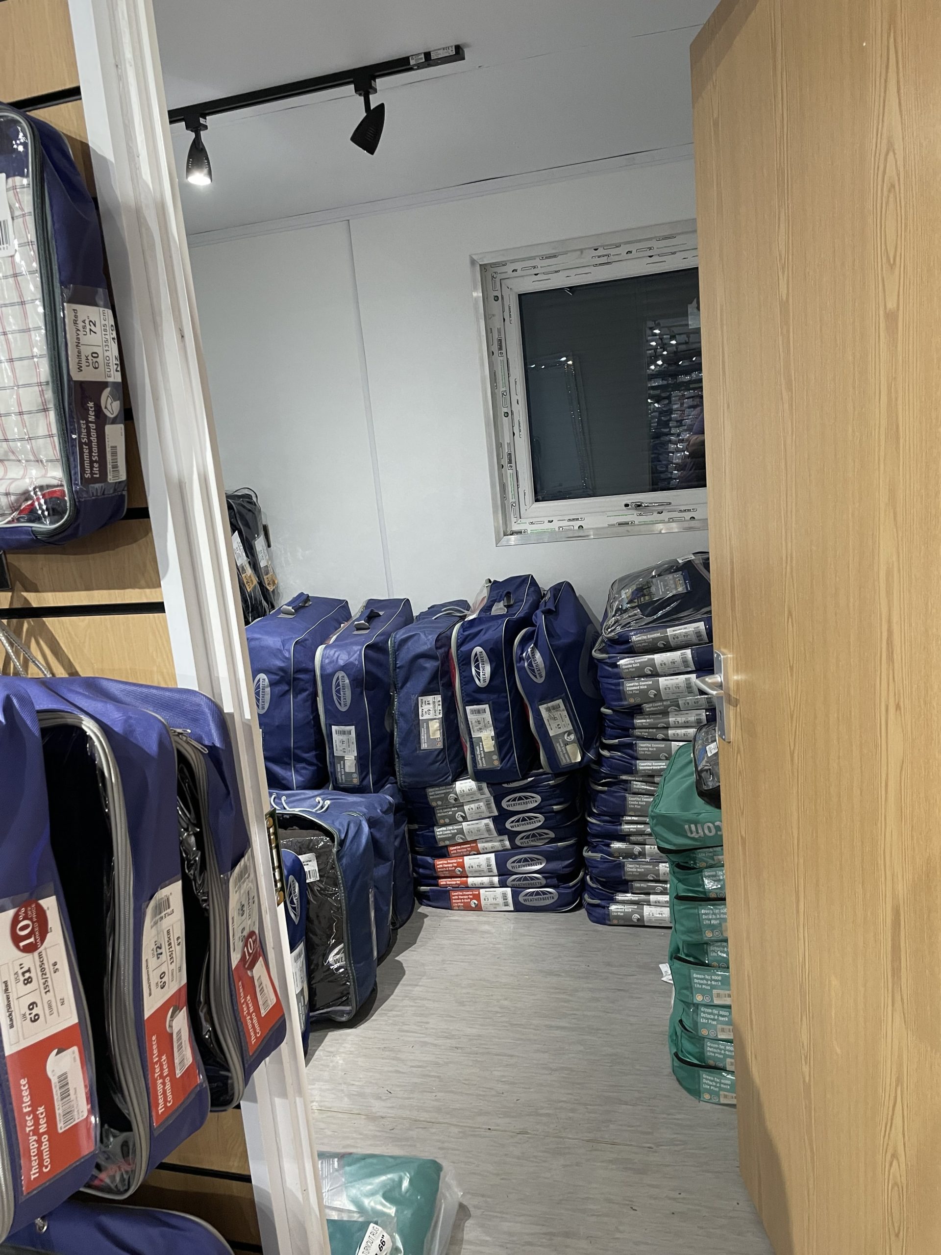
Hallway leading into:
Transport can be arranged please ask.


Location: Nationwide
Not Available for Hire
Call for an instant quote!
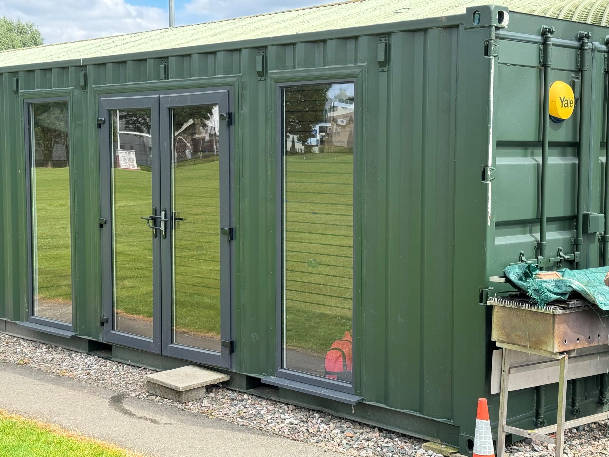
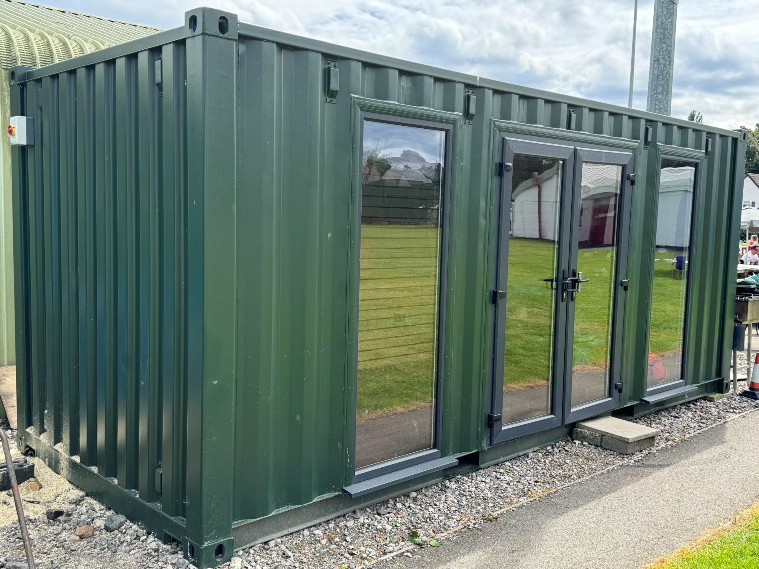
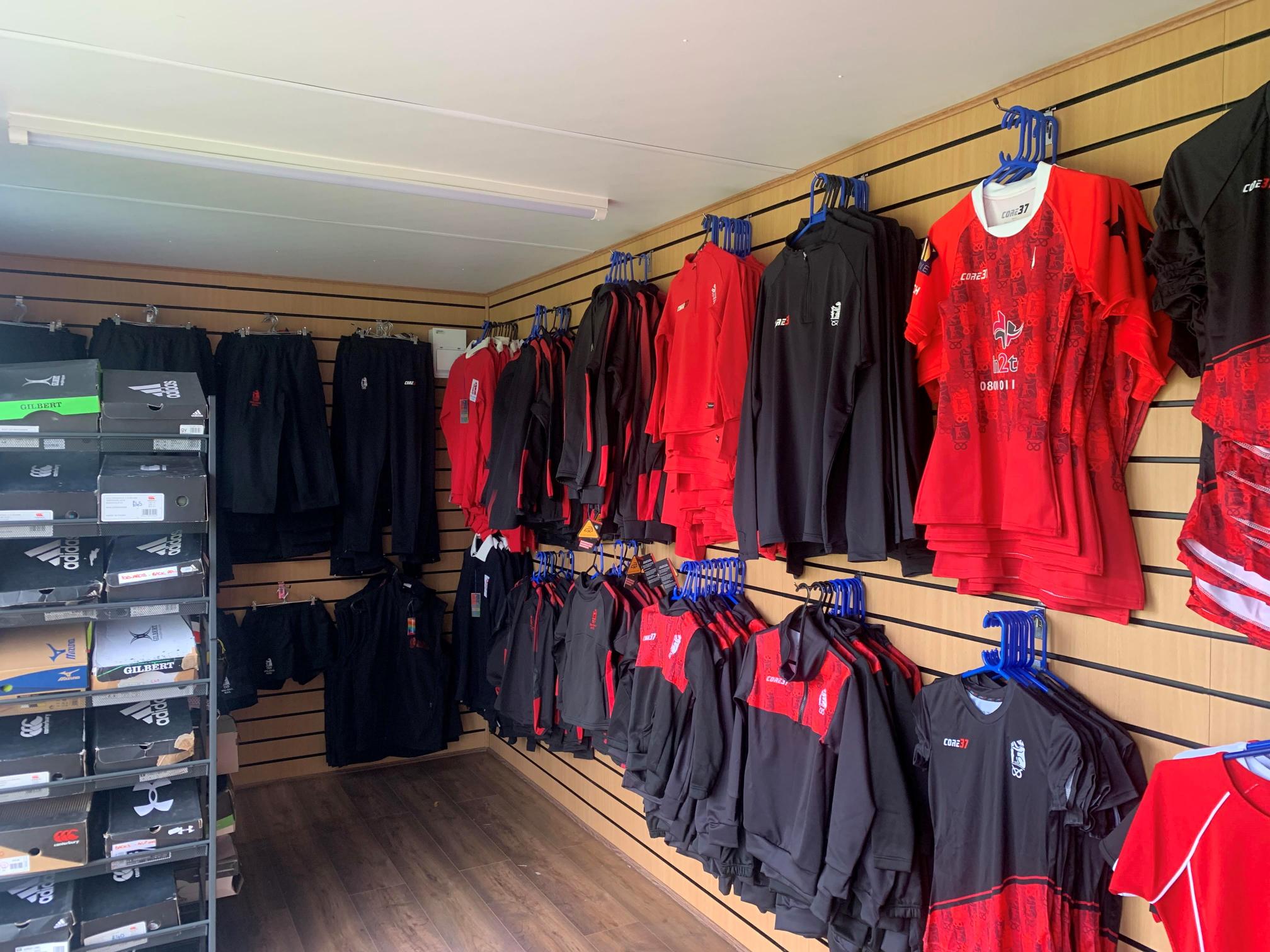
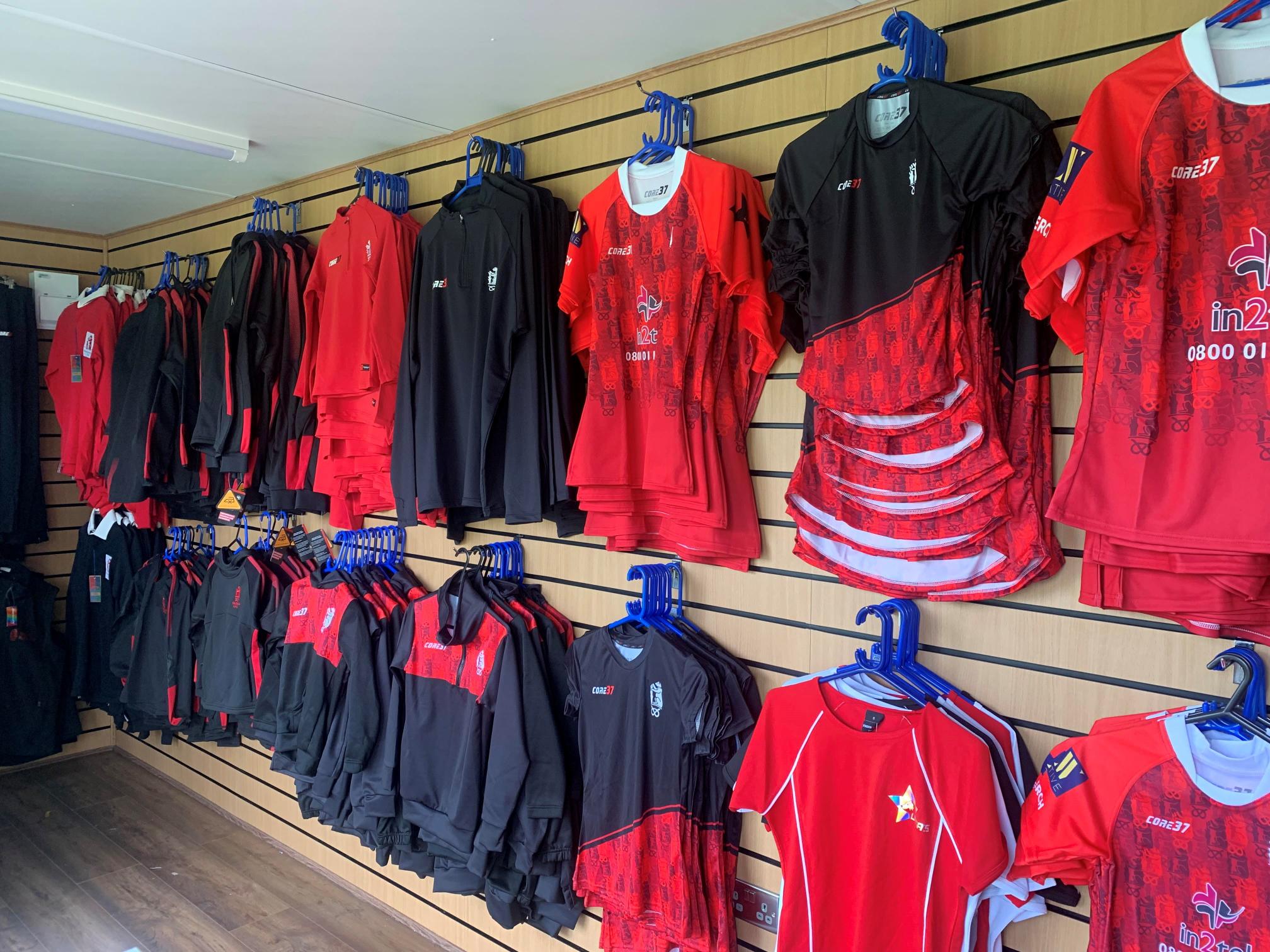
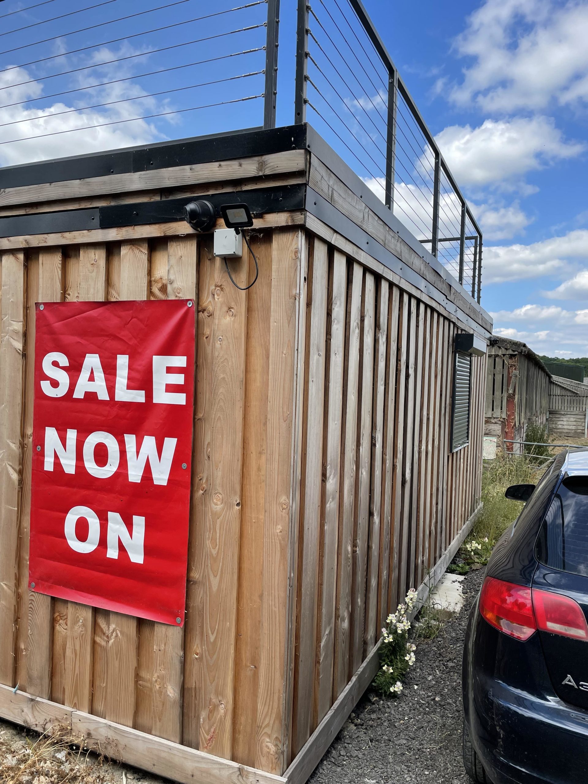
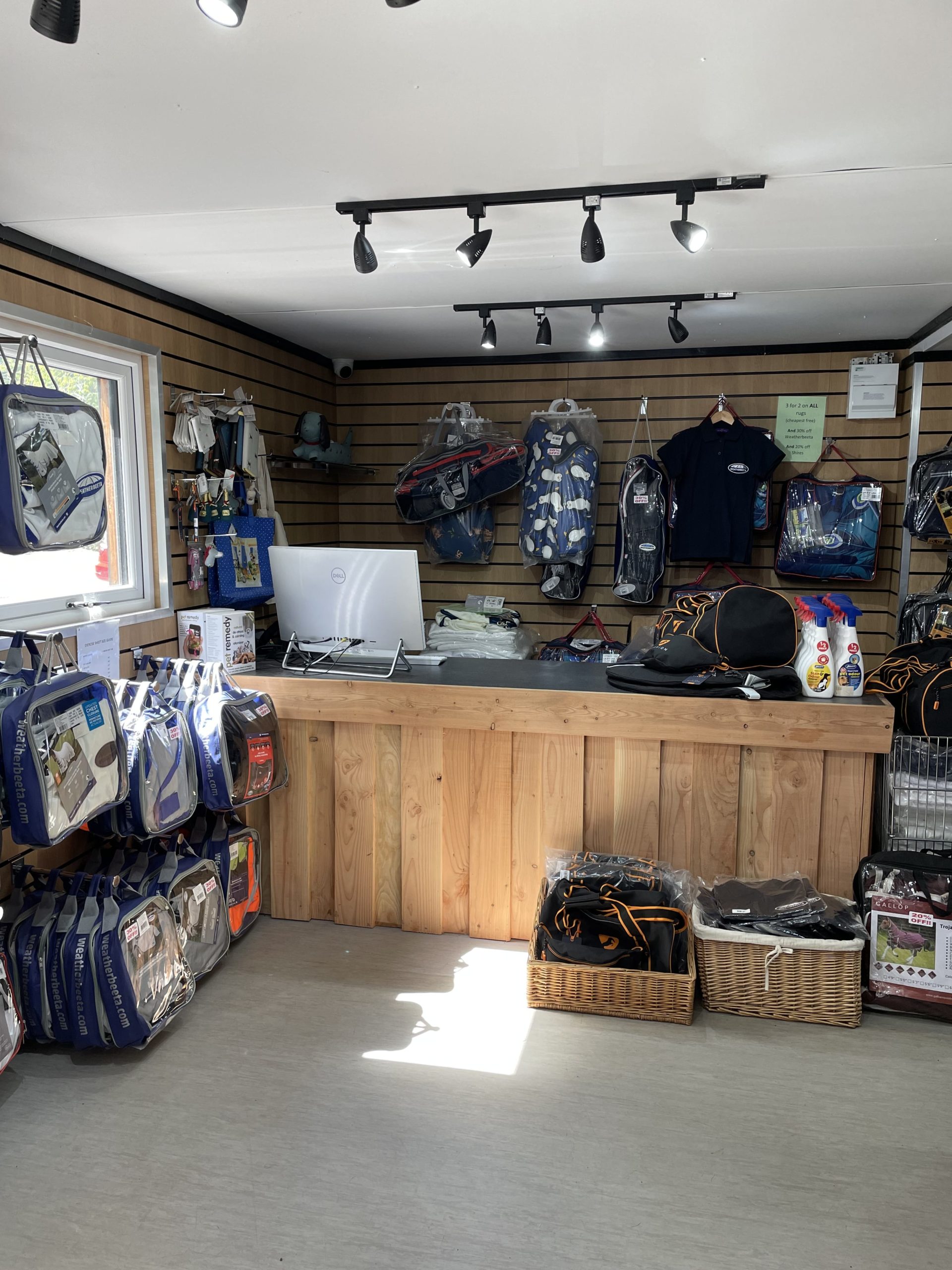
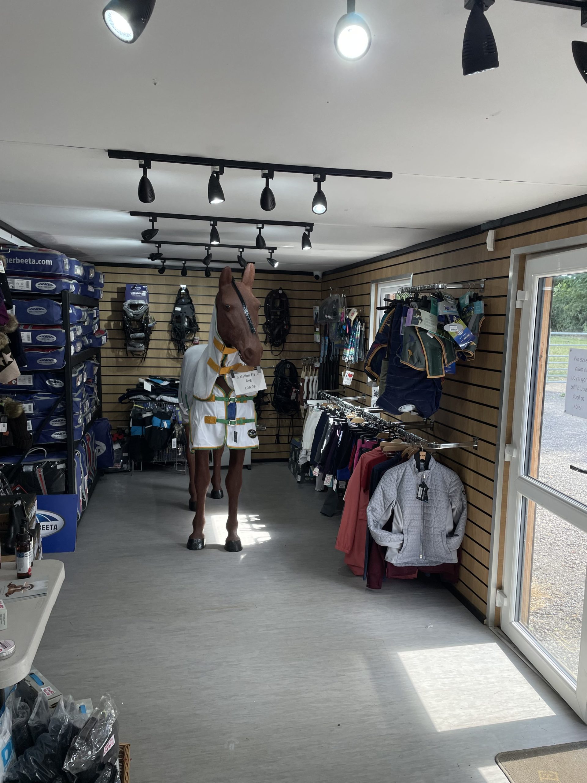
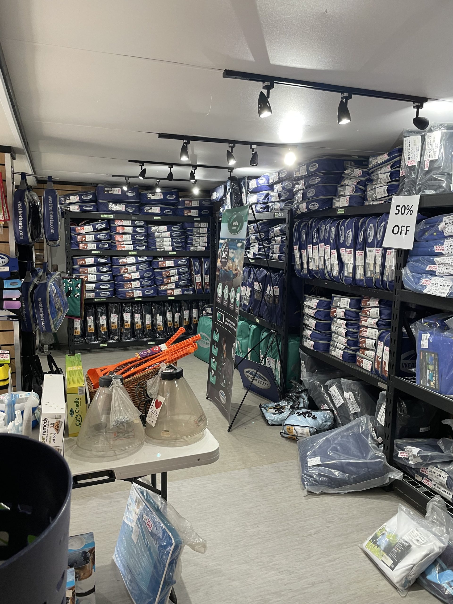
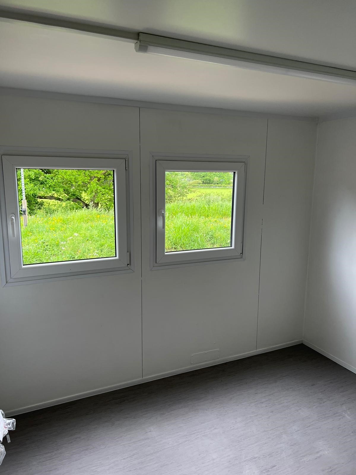
20ft x 8ft Container Conversion Retail Shop
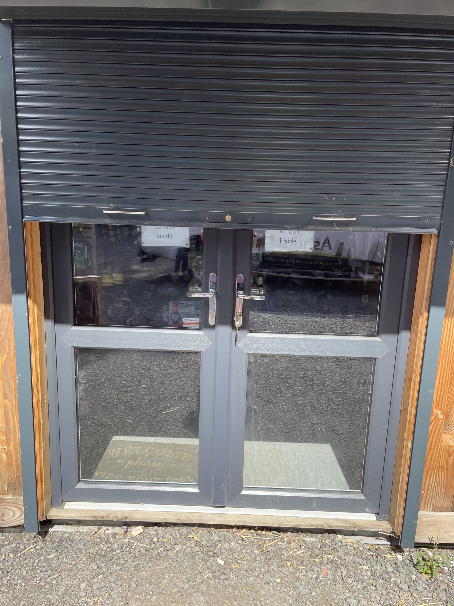
UPVC Double glazed Windows + French Doors
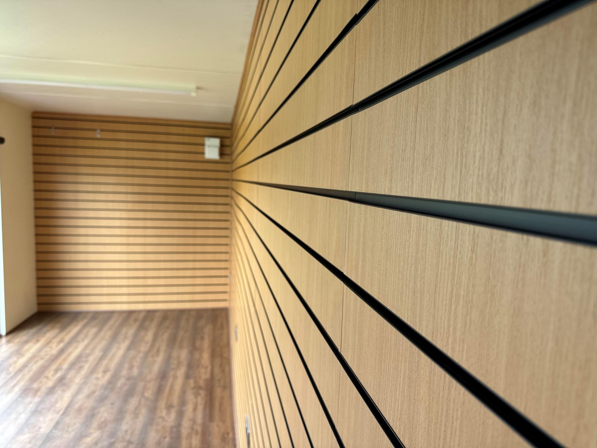
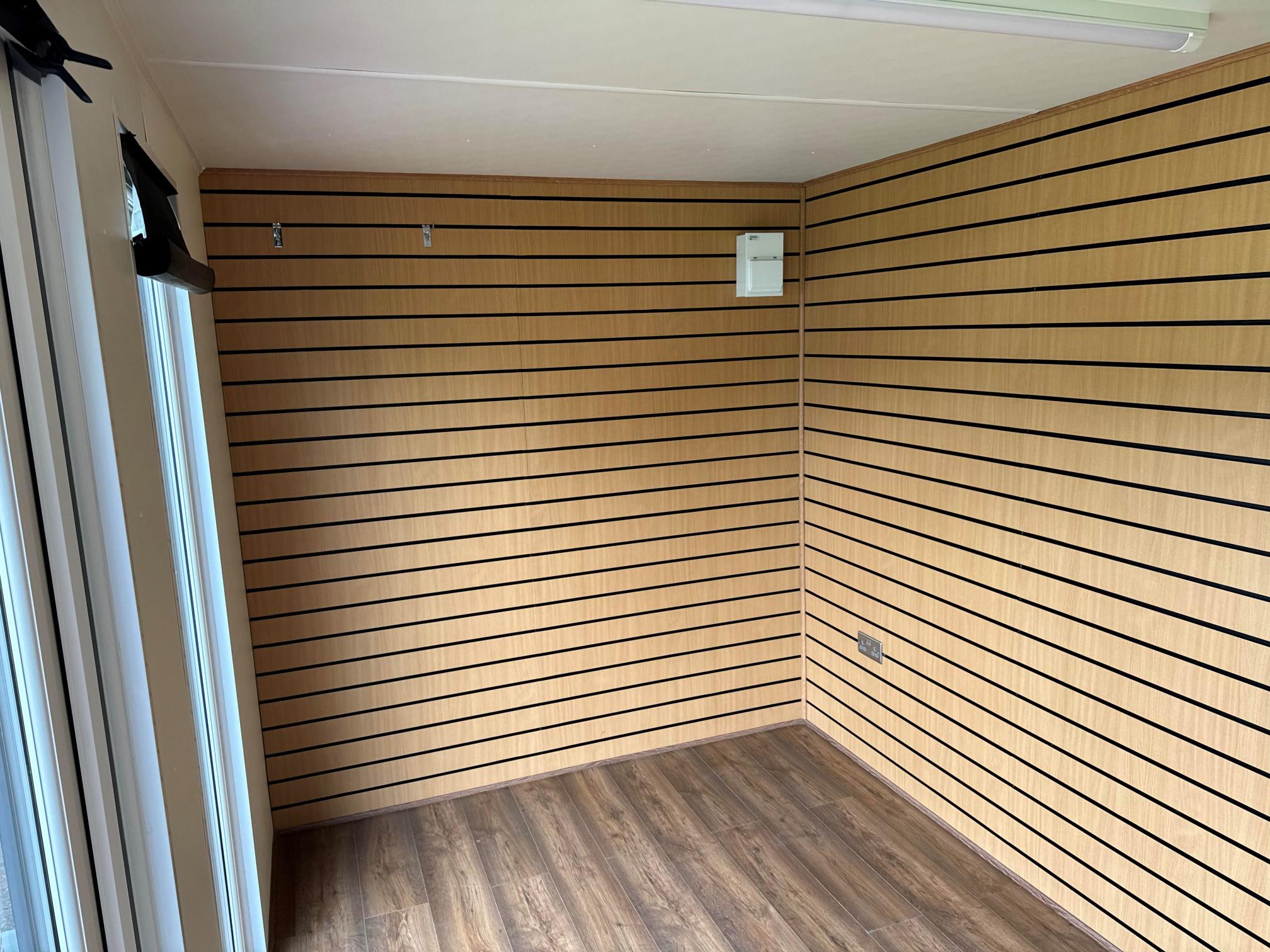
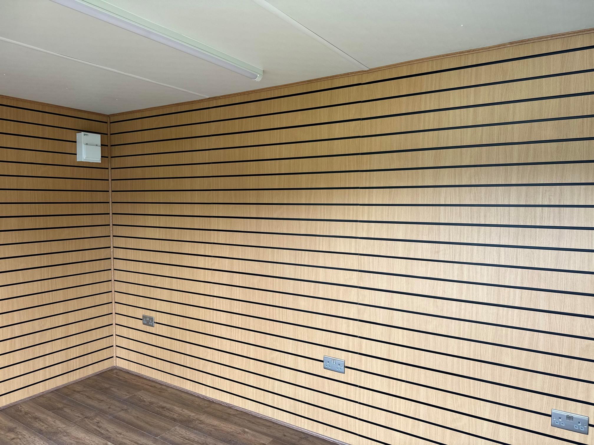
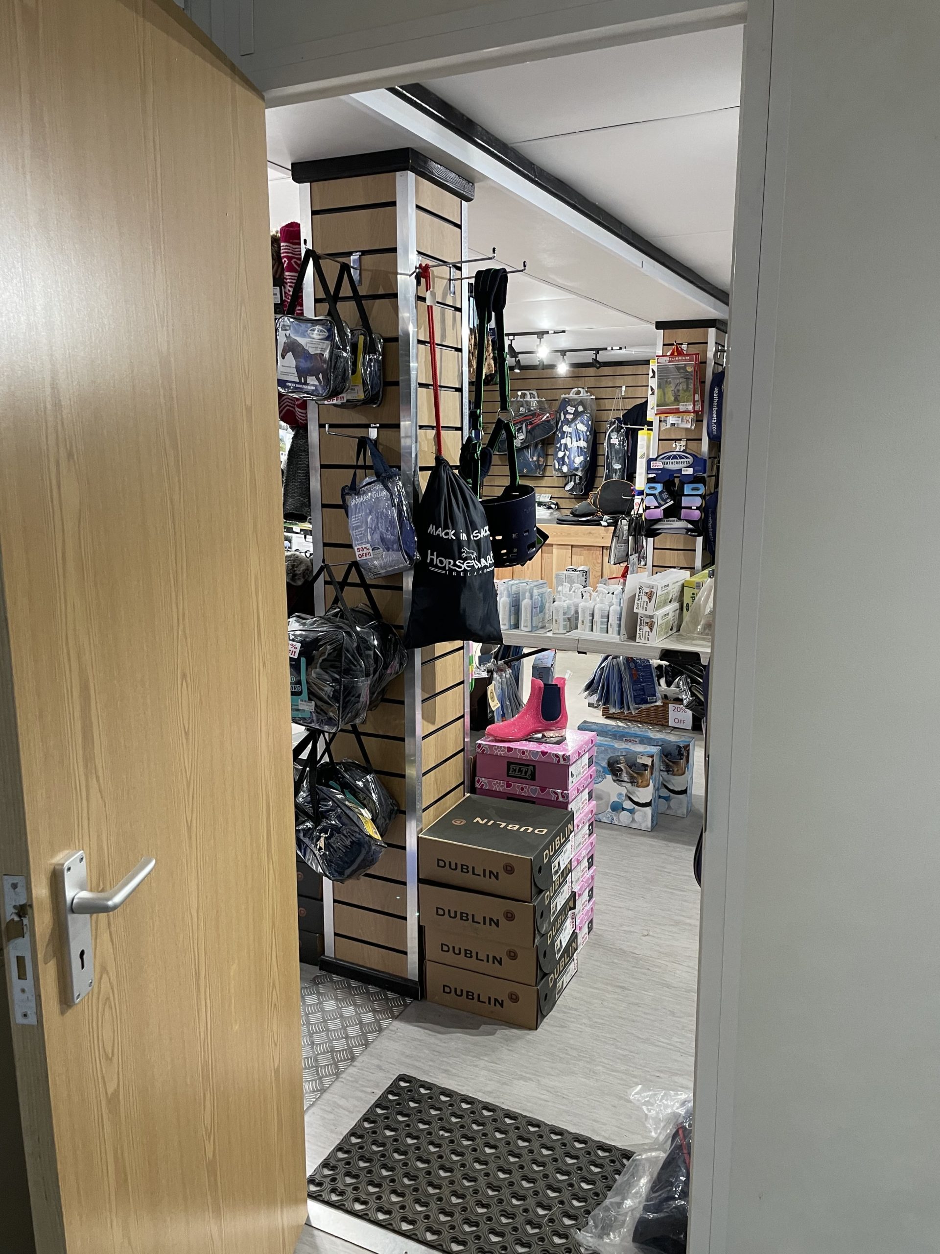
Slat Wall for retail fixings and Merchandise
Electric Chrome Sockets, led lighting and heating.
Laminate Flooring
12 months Warranty
Maintenance call out package included
Less than 2 years old
Still in Brand New Condition


Fully refurbished
Colour light grey
Slate grey anthracite upvc double glazed windows


Location: Nationwide
+ VAT
Not Available for Hire
Call for an instant quote!
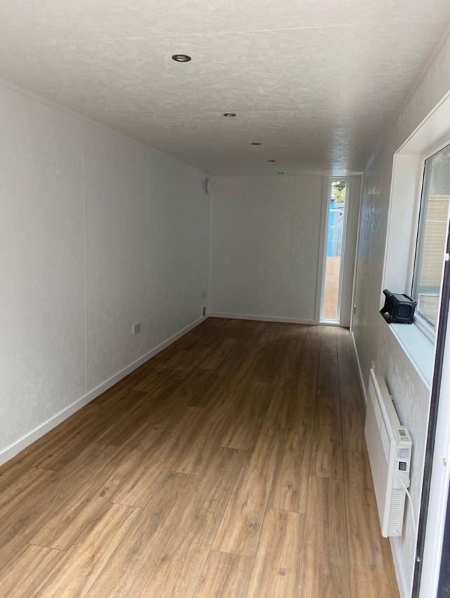
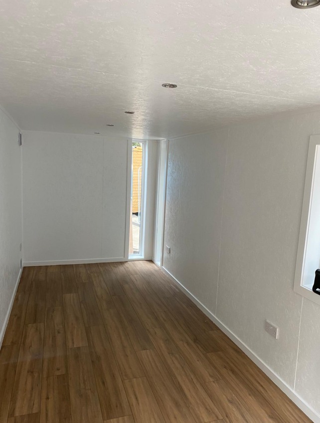
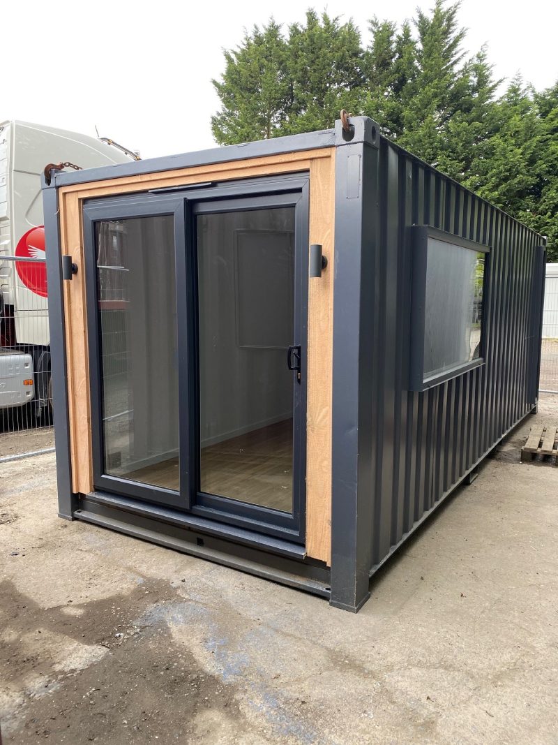
Fully Insulated with electric sockets, spot lighting, and heating
Wood Flooring
UPVC Sliding Door + Windows
Lead Time for build 6-8 weeks


Location: Nationwide
+ VAT
Not Available for Hire
Call for an instant quote!
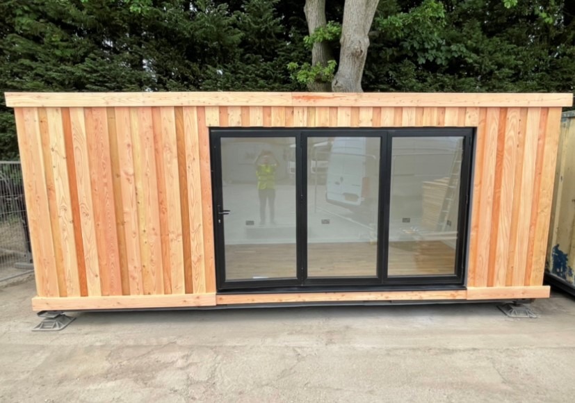
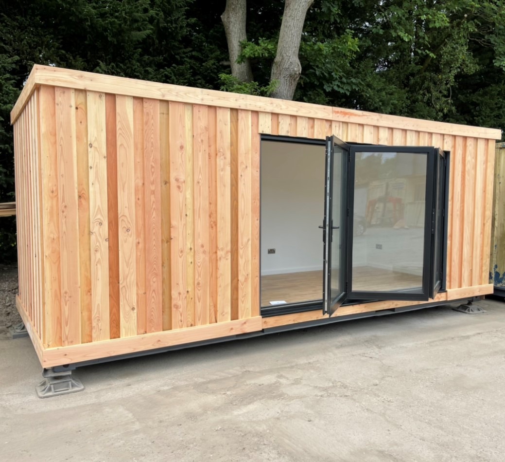
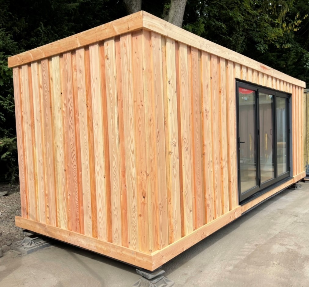
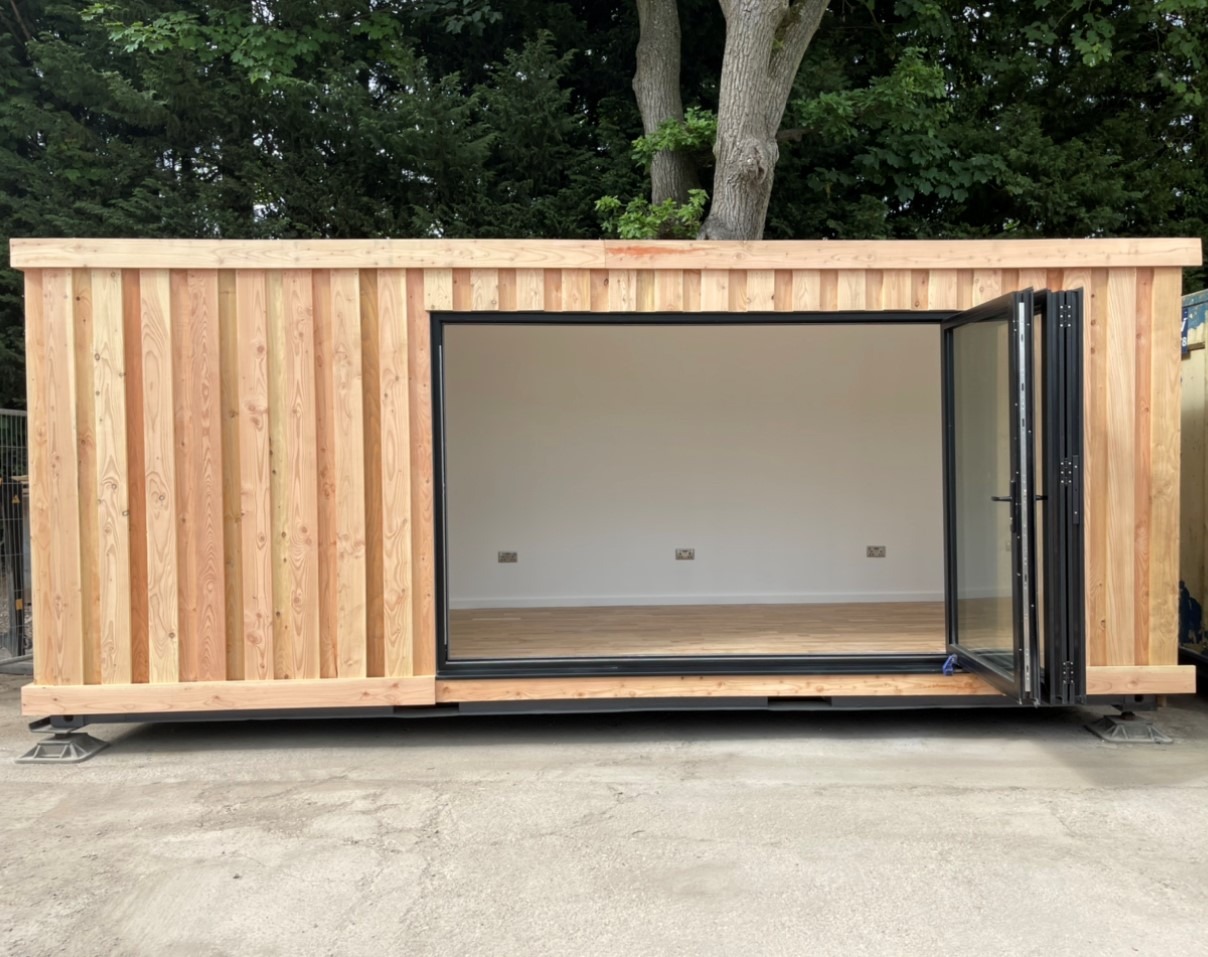
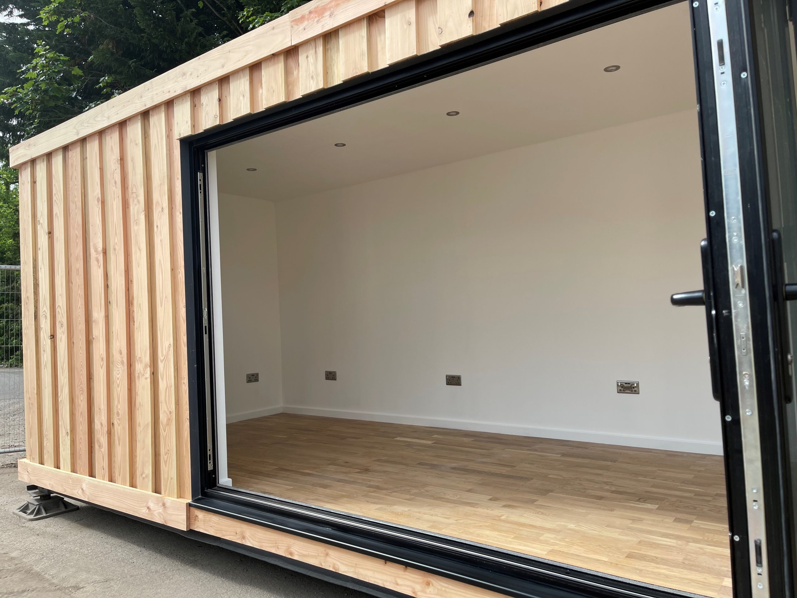
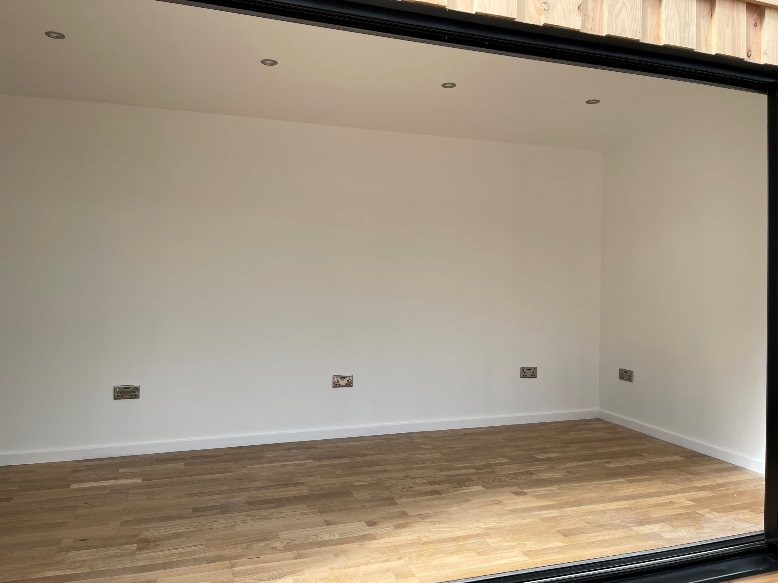
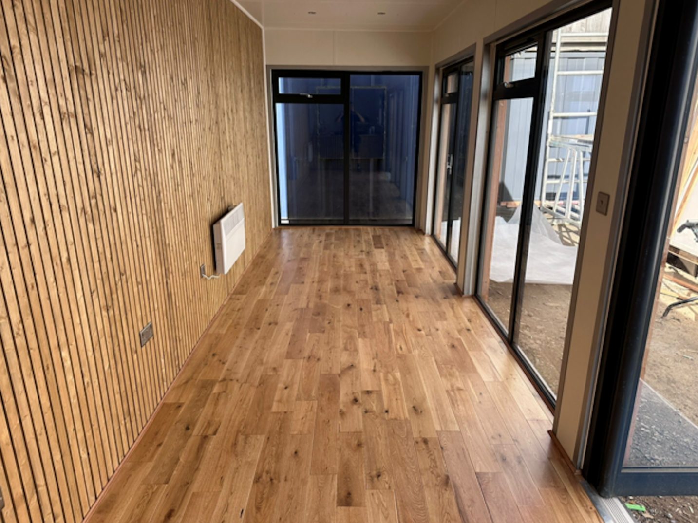
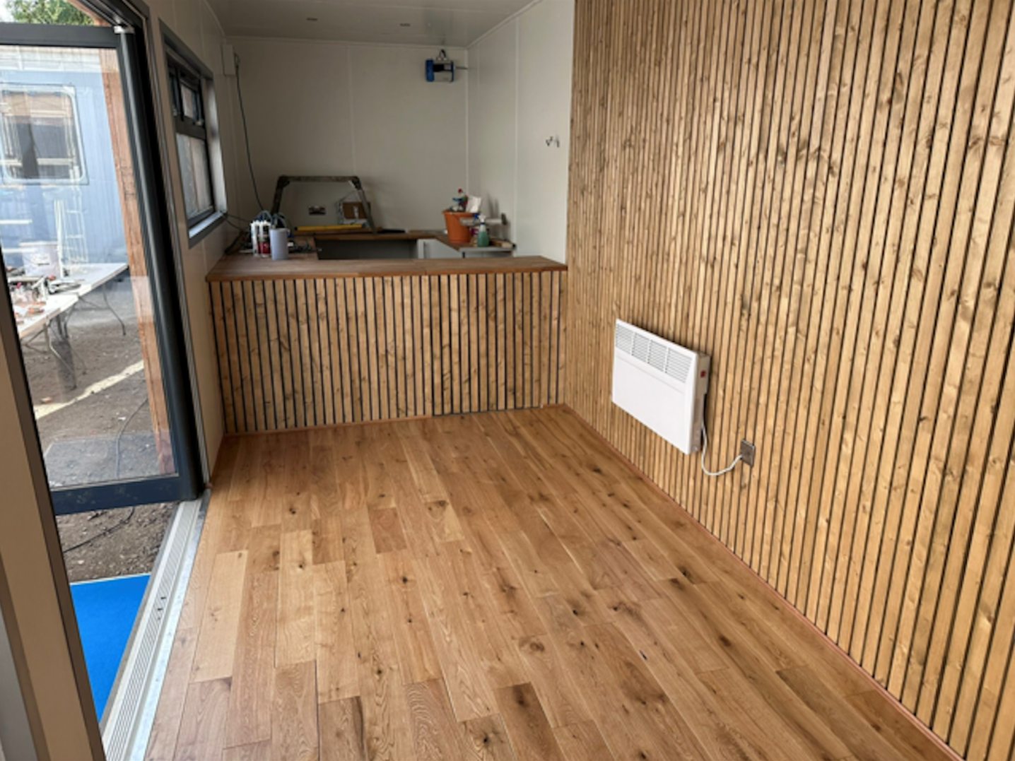
Fully Insulated with electric sockets, spot lighting, and heating
Wood Flooring
Aluminium Bi Fold Doors
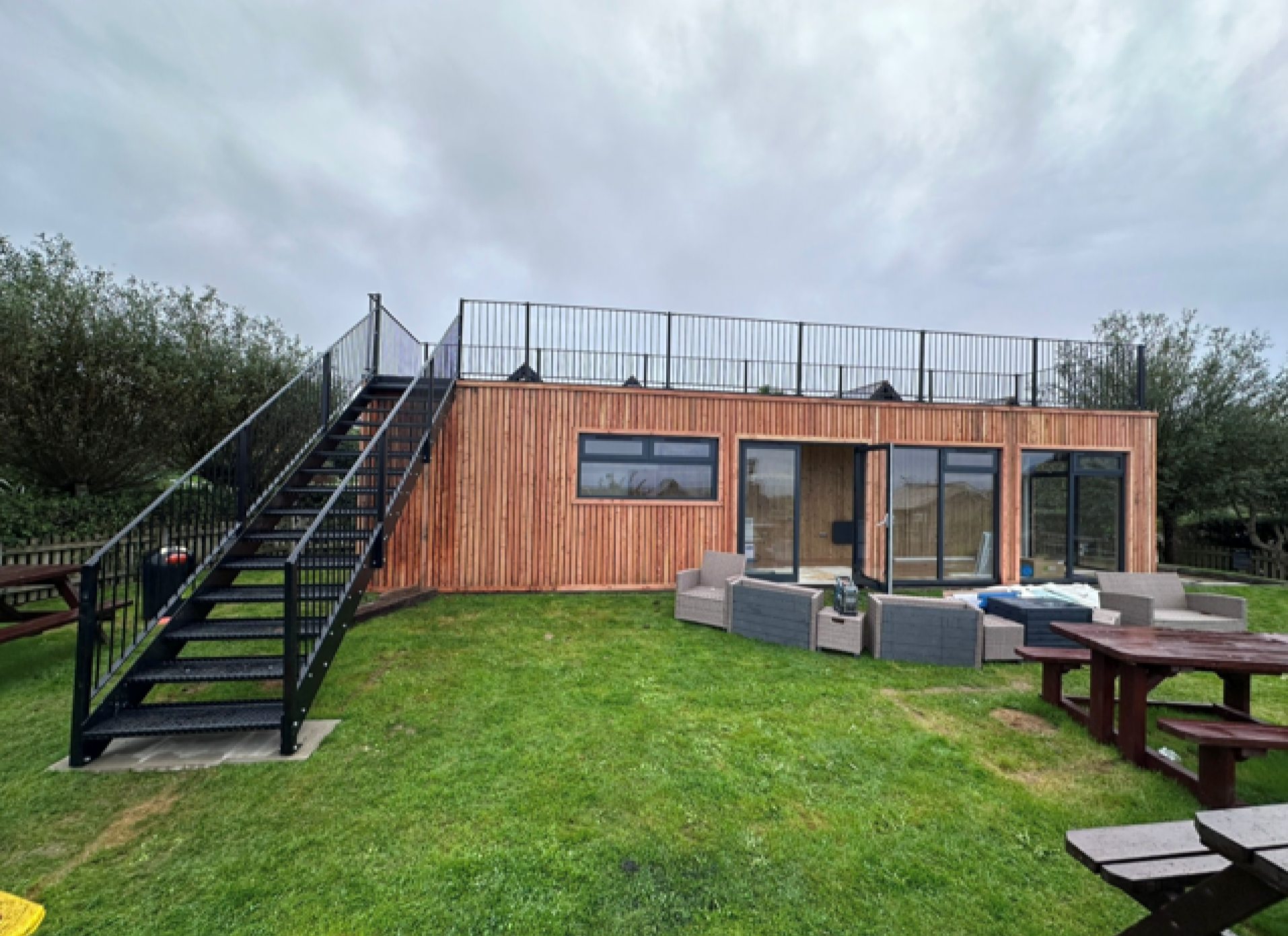
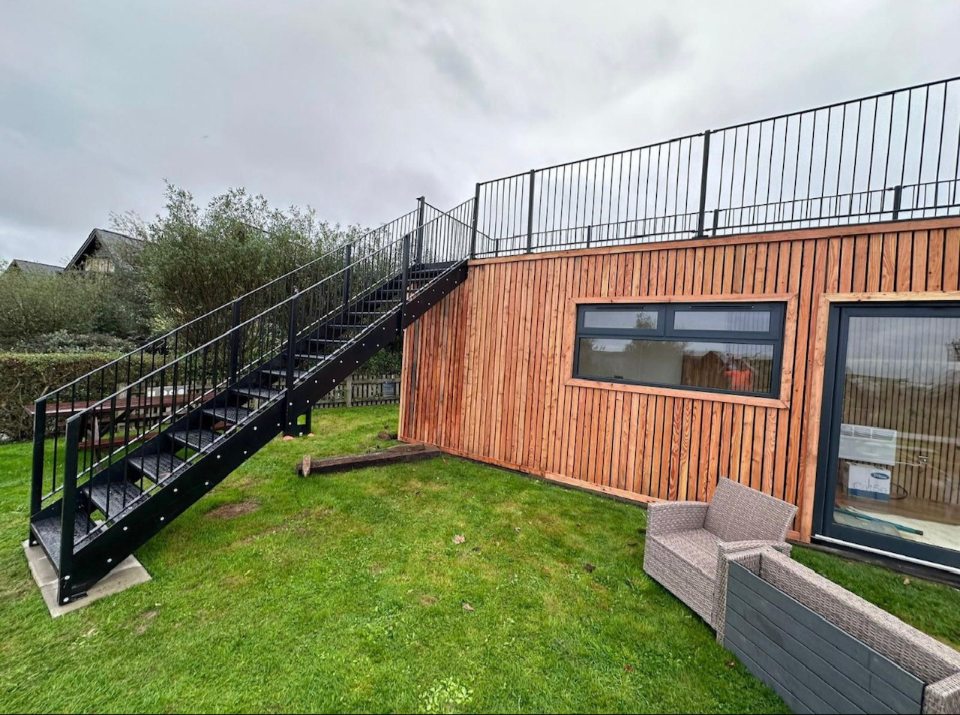
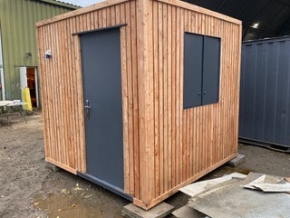
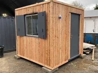
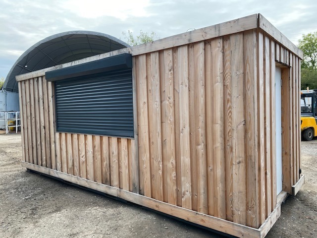
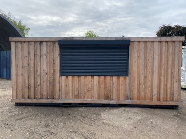
Fully wrapped in larch cladding
Lead Time for build 6-8 weeks


Location: Nationwide
+ VAT
Not Available for Hire
Call for an instant quote!
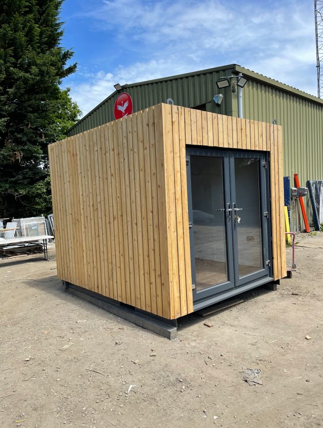
Fully Insulated with electric sockets, spot lighting, and heating
Wood Flooring
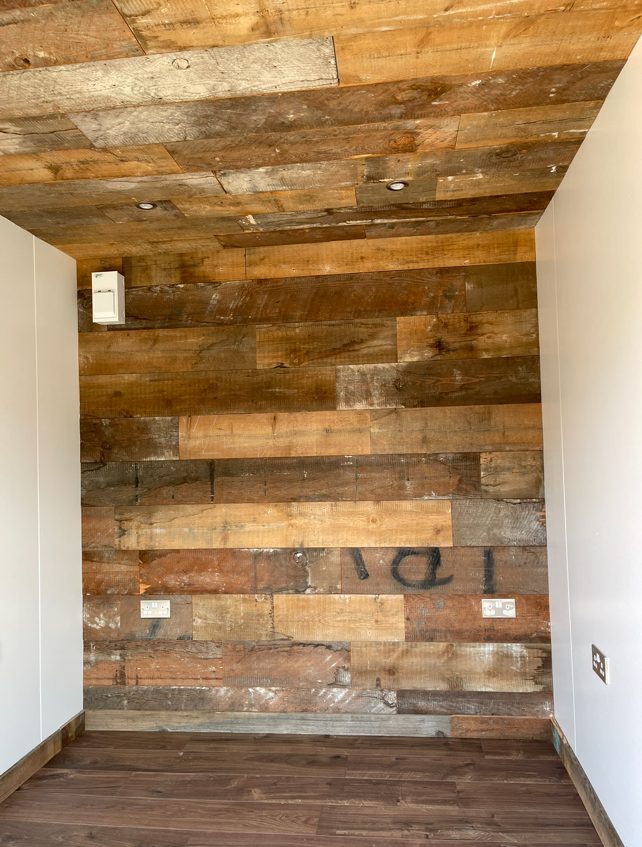
Feature Clad Wall and Ceiling
UPVC Double glazed French Doors
Fully wrapped in larch cladding
Lead Time for build 6-8 weeks


Location: Nationwide
EX VAT
Not Available for Hire
Call for an instant quote!


Location: Nationwide
EX VAT
Not Available for Hire
Call for an instant quote!


Location: Nationwide
EX VAT
Not Available for Hire
Call for an instant quote!


Location: Nationwide
EX VAT
Not Available for Hire
Call for an instant quote!


Location: Nationwide
EX VAT
Not Available for Hire
Call for an instant quote!

Location: Nationwide
EX VAT
Not Available for Hire
Call for an instant quote!


Location: Nationwide
EX VAT
Not Available for Hire
Call for an instant quote!


Location: Nationwide
EX VAT
Not Available for Hire
Call for an instant quote!


Location: Nationwide
EX VAT
Not Available for Hire
Call for an instant quote!


Location: Nationwide
EX VAT
Not Available for Hire
Call for an instant quote!


Location: Nationwide
EX VAT
Not Available for Hire
Call for an instant quote!


Location: Nationwide
EX VAT
Not Available for Hire
Call for an instant quote!


Location: Nationwide
EX VAT
Not Available for Hire
Call for an instant quote!


Location: Nationwide
EX VAT
Not Available for Hire
Call for an instant quote!


Location: Nationwide
EX VAT
Not Available for Hire
Call for an instant quote!


Location: Nationwide
EX VAT
Not Available for Hire
Call for an instant quote!
10ftx8ft – £5950 + Vat / 16ftx8ft – £7950 + Vat / 20ftx8ft – £9000 + Vat / 24ftx8ft – £12000 + Vat / 30ftx8ft – £13500 + Vat


Location: Nationwide
EX VAT
Not Available for Hire
Call for an instant quote!


Location: Nationwide
EX VAT
Not Available for Hire
Call for an instant quote!


Location: Nationwide
EX VAT
Not Available for Hire
Call for an instant quote!

Location: Nationwide
Quantity: ∞
EX VAT
Not Available for Hire
Call for an instant quote!
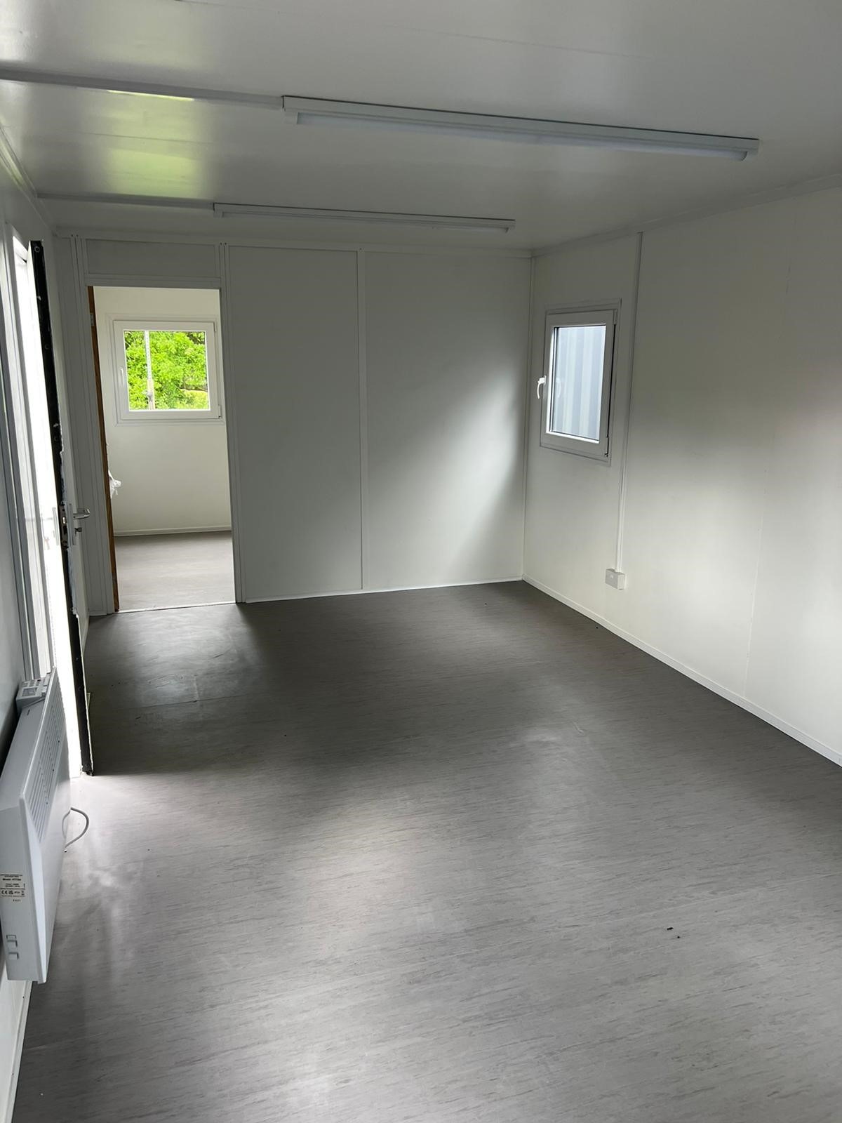
• Reinforced doors and windows with secure locking
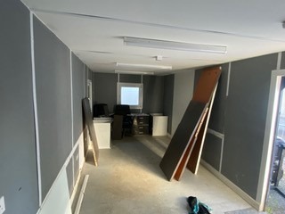
• Open plan with electric sockets and lighting
• Ral Code Colour of choice
• Any Extras available : Canteen, Partitions, Toilets.

Location: Nationwide
EX VAT
Not Available for Hire
Call for an instant quote!
• Reinforced doors and windows with secure locking
• Open plan with electric sockets and lighting
• Ral Code Colour of choice
• Any Extras available : Canteen, Partitions, Toilets.
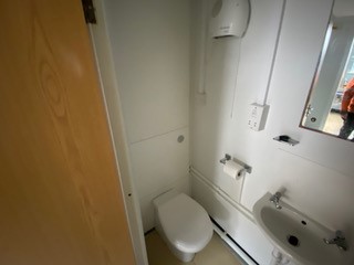
• Reinforced doors with secure locking
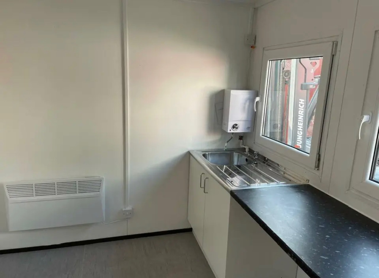
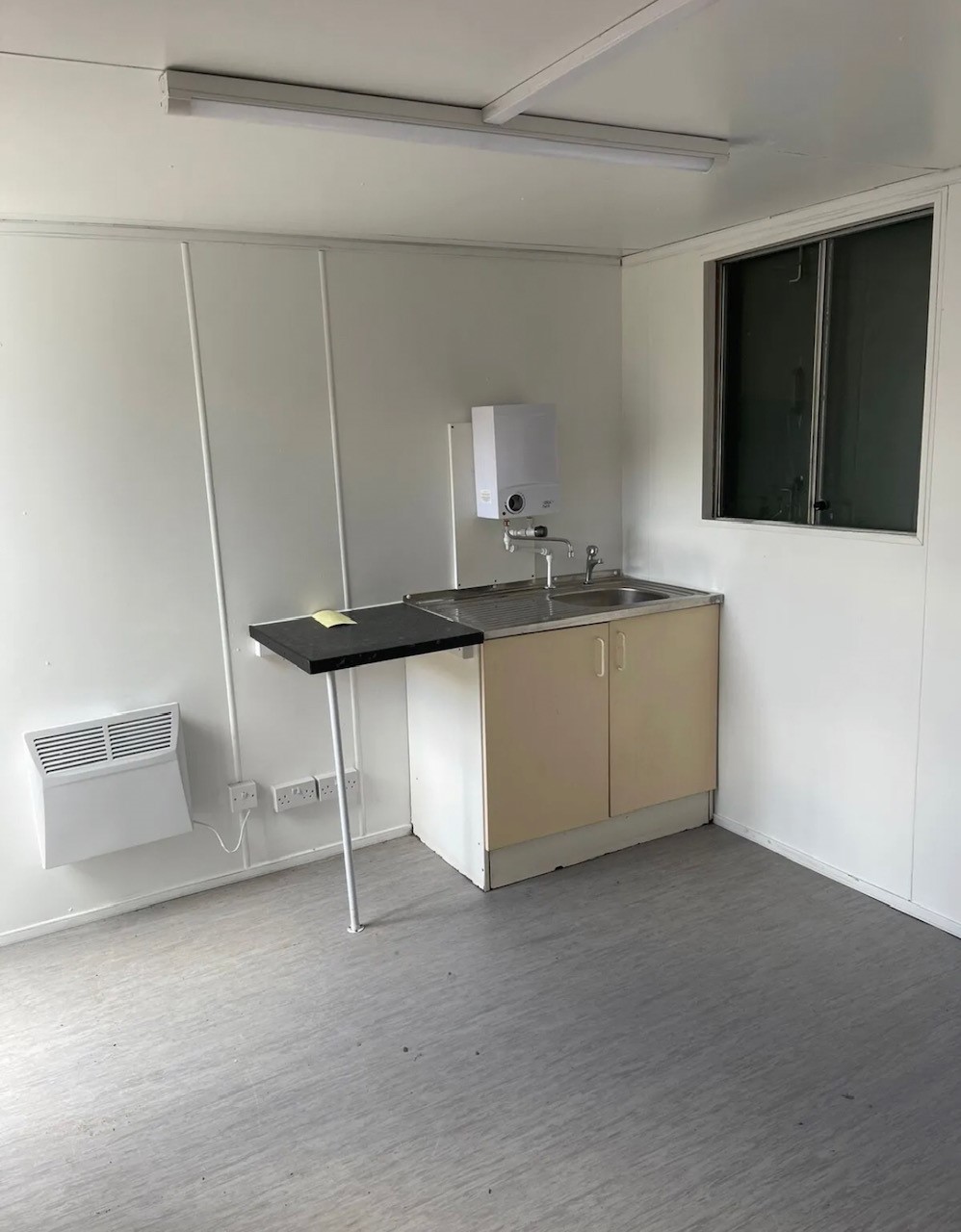
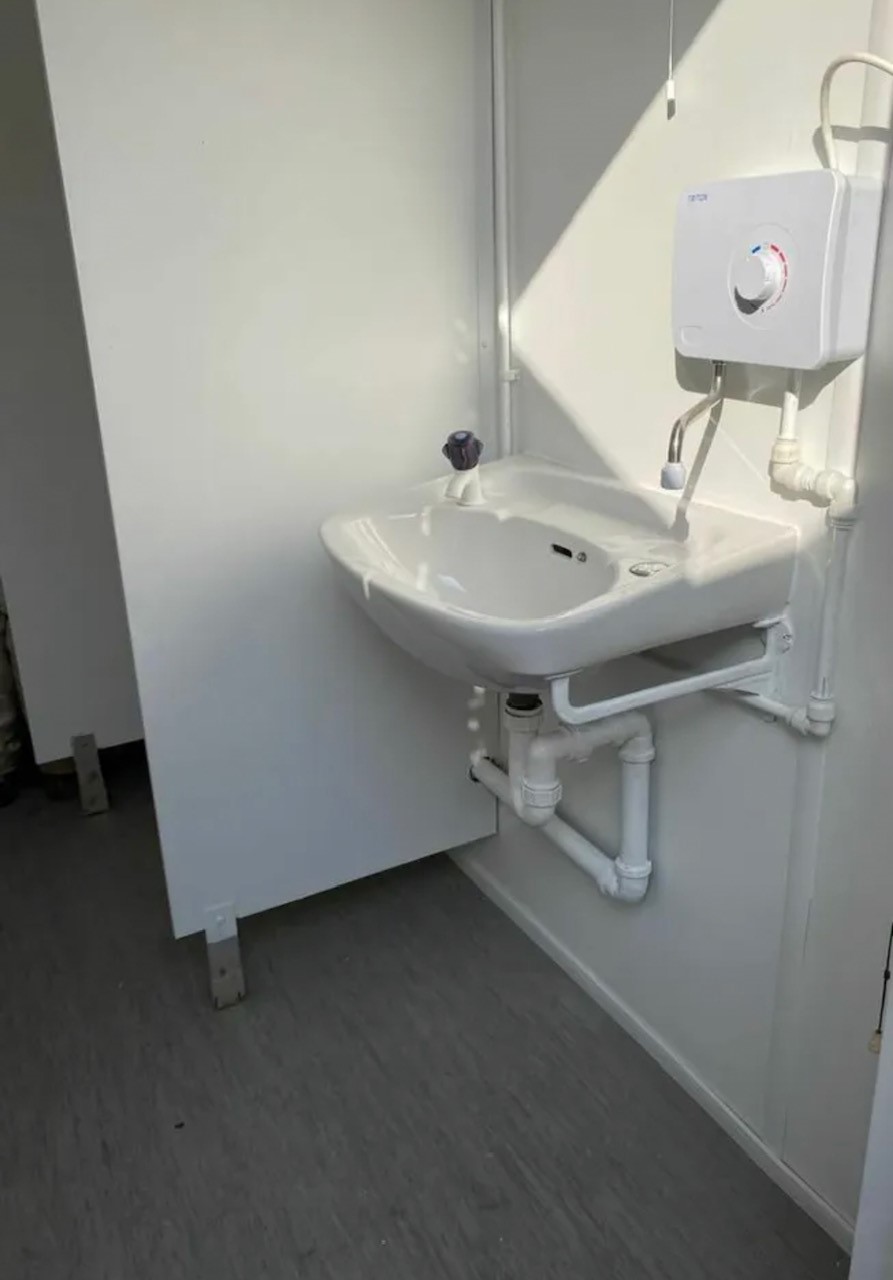
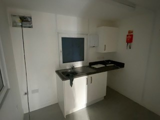
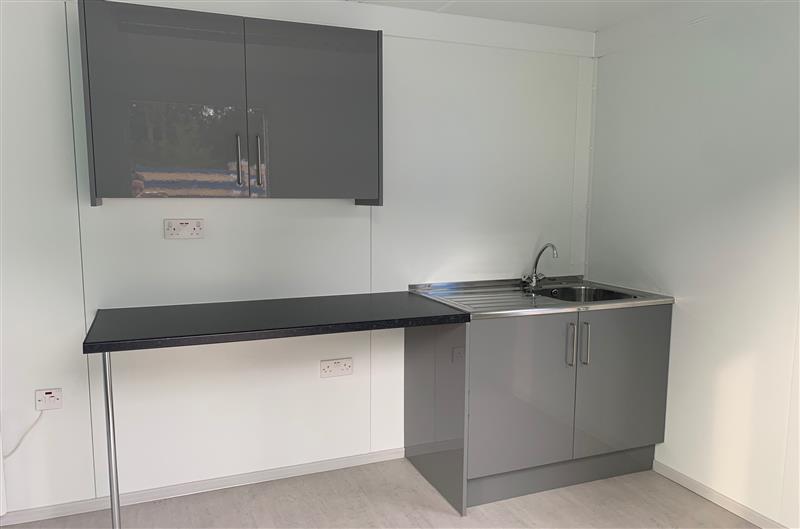
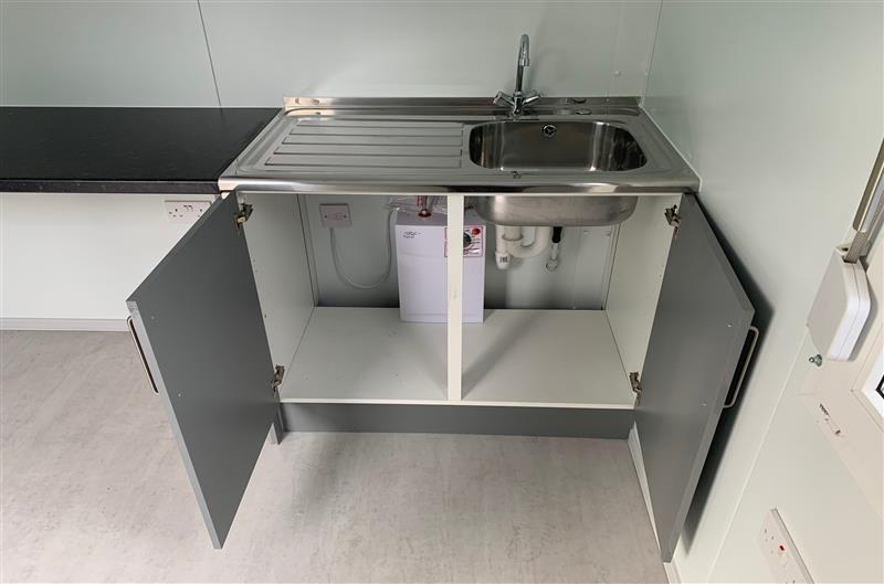
• Sink and water boiler included


Location: Nationwide
Quantity: ∞
EX VAT
Not Available for Hire
Call for an instant quote!


Location: Nationwide
EX VAT
Not Available for Hire
Call for an instant quote!
Get a Quick Container Quote Now!


Location: Nationwide
EX VAT
Not Available for Hire
Call for an instant quote!
Get a Quick Container Quote Now!