Choosing the right antenna is not just a matter of buying the one with the highest gain. A Sma Antenna must match your device, operating frequency, and installation conditions. Small details matter. Connector size, gender, and polarity can determine whether it fits safely; SMA and RP-SMA connectors may look similar but are not interchangeable in every setup.
Start with the frequency range listed in your device’s manual or antenna datasheet. An antenna designed for 2.4 GHz may perform poorly on a different band, even if its connector fits. Check impedance too: many radio systems use 50 ohms. Then consider gain and radiation pattern. Higher gain can help in some directions, but it may narrow coverage elsewhere. A small indoor antenna on a desk has different needs from one mounted outdoors above a roofline.
Cable length and placement also affect results. A long, thin cable can introduce signal loss, while nearby metal surfaces may change an antenna’s performance. In practical installations, the best choice often depends on the actual layout, not just the specifications. A datasheet is a useful starting point, though it cannot capture every room or mounting position. If performance matters, compare signal readings in the intended location and consult the equipment manufacturer’s guidance. I would not treat one test as conclusive; moving an antenna a few centimeters can sometimes change the result. This guide outlines the checks that help narrow your options without promising a perfect match.
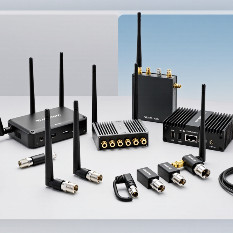
An SMA label identifies the connector, not the antenna’s operating frequency. Check the radio’s exact channel plan before choosing an antenna. In the United States, FCC Part 15.247 covers 2,400–2,483.5 MHz, an 83.5 MHz span often used for 2.4 GHz devices. Check the antenna’s specified frequency range and VSWR or return-loss data. A plug that fits is not proof of a good match.
For 5 GHz, identify the actual channels and regional allocation; “5 GHz” is not one narrow target. ITU-R Recommendation P.525-4 provides a free-space path-loss calculation: at equal distance, a 5.0 GHz signal has about 6.4 dB more path loss than a 2.4 GHz signal. Indoors, walls, cables, and antenna orientation also affect performance. That number is a useful guide, not a prediction of every room.
Check the real band. If possible, measure the antenna at its feed point with a vector network analyzer, then repeat the test with the enclosure and ground plane in place. A compact build may shift noticeably when its lid is fitted; bench measurements alone can mislead. For dual-band radios, look for documented coverage and efficiency at both target bands. A “dual-band” label alone proves little.

How to Choose the Right SMA Antenna?
Match the antenna’s 50 Ω impedance to the radio, cable, and test equipment. A mismatch can increase reflected power and weaken the signal reaching the receiver. Check the specified frequency range, then confirm the connector rating covers it. DC–18 GHz is common for many SMA connections, but it is not a guarantee for every assembly. Antenna performance also depends on mounting, nearby metal, and cable length.
Read the antenna and connector data sheets together. Confirm whether the connector is SMA or a similar-looking variant; incompatible interfaces may damage delicate threads. Look for return loss or VSWR across the frequencies you plan to use, not just at one test point. A headline rating can hide uneven performance near the band edges. That detail is easy to overlook. I would also recheck the full cable-and-adapter path, since each added connection can affect the match.
Tips: Inspect the center pin and threads before mating. Tighten gently with the specified torque, if provided. Keep the cable bend gradual, and retest after installation. A tidy bench setup may behave differently once the antenna sits beside a metal panel.
When comparing SMA antennas, treat gain, polarization, and VSWR as one system, not three isolated specifications. Gain in dBi is referenced to an ideal isotropic radiator; it does not guarantee the same range in every installation. A metal enclosure, a hand, or a nearby cable can reshape the radiation pattern. Small details matter.
A 2:1 VSWR corresponds to a reflection coefficient magnitude of one-third and a return loss of about 9.54 dB. About 11.1% of incident power reflects, while mismatch loss is roughly 0.51 dB. These values follow standard transmission-line calculations. IEEE Std 149-2021 describes antenna measurement practices, so check the test setup and frequency band alongside the headline VSWR. A lab result can shift on your device.
Polarization alignment matters, too. Ideal orthogonal linear polarization can cause severe loss, though reflections may change real-world results. Compare gain at your operating frequency, account for cable loss, and inspect VSWR across the full band. IEEE Std 145-2013 defines antenna terminology, but one peak-gain figure cannot describe an installed link. I would still question the habit of choosing the lowest VSWR alone; a good match does not ensure the antenna’s pattern points energy where the receiver needs it.
Start with the mating interface, not the listing photo. A standard SMA plug usually has a center pin, while its jack has a socket. Reverse-polarity versions can look deceptively similar, so check the contact and interface drawing against IEC 61169-15, the SMA connector specification. Threads alone are not enough. A mismatched pair may tighten but fail electrically, a mistake that can slip past a quick bench check.
For mounting, measure the panel-hole diameter, panel thickness, and clearance behind the surface. A bulkhead jack needs room for its nut and cable; a magnetic-base antenna needs a flat, stable metal surface. Check the cable’s bend radius too. A tight bend beside the connector can strain the joint. It is easy to overlook.
Treat the IP rating as a property of the installed assembly, not just the antenna. IEC 60529 defines IP code tests: IP67 means dust-tight protection and temporary immersion in water up to one metre for 30 minutes under specified test conditions. That rating does not automatically cover an unsealed panel cutout or a loose connector. Check the gasket, mating connection, and mounting instructions together. The standard’s water test also does not establish resistance to every spray, chemical, or outdoor exposure.
Cable loss can quietly reduce the signal reaching an SMA antenna. It also weakens the reflected signal returning to your test equipment. That can make an antenna appear better matched than it really is. Short cables help, but they do not remove the need to check loss.
Start with the cable’s specified attenuation at your operating frequencies, not just one headline figure. A cable that performs well near the band’s center may lose more at its upper edge. Note the cable length, connector condition, and any adapters in the test path. Small details matter. A loose connector can change a measurement, and repeated reconnecting may produce slightly different results.
Measure across the full operating band with a calibrated network analyzer. When possible, calibrate at the antenna’s SMA connection, or compensate for the cable’s measured loss. Record return loss or VSWR at several points, including both band edges. Then compare results with the antenna’s intended frequency range and your device’s requirements. A single good reading is not enough. Real installations may differ from a tidy bench setup, especially when nearby surfaces or cables affect the antenna. I would treat an unexpected result as a reason to check the setup again, not as proof that the antenna is faulty.
Registered in England & Wales No. 2786496
Registered office at: 337 Tanworth Lane,
Shirley, Solihull, B90 4DU
Registered for VAT, registration No.
GB 655 1347 38


Location: Nationwide
Not Available for Hire
We can deliver for a cost please ask and send us post code.
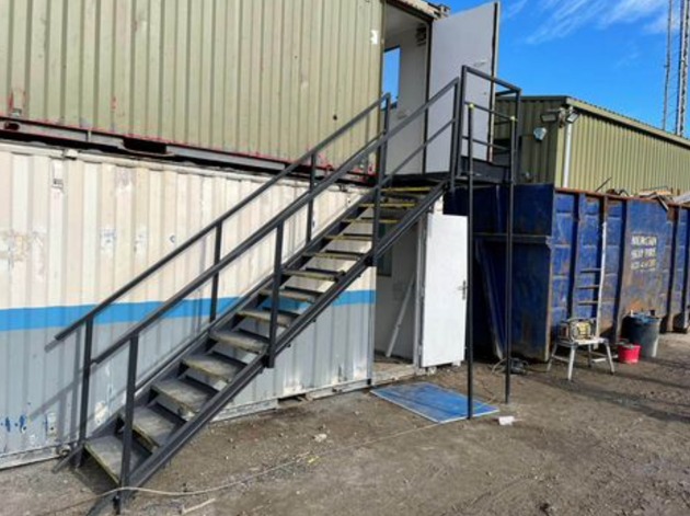
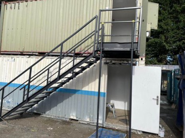
13 tread
14 tread
15 tread


Location: Nationwide
Not Available for Hire
Call for an instant quote!


Location: Nationwide
Not Available for Hire
We can deliver for a cost please ask and send us post code.
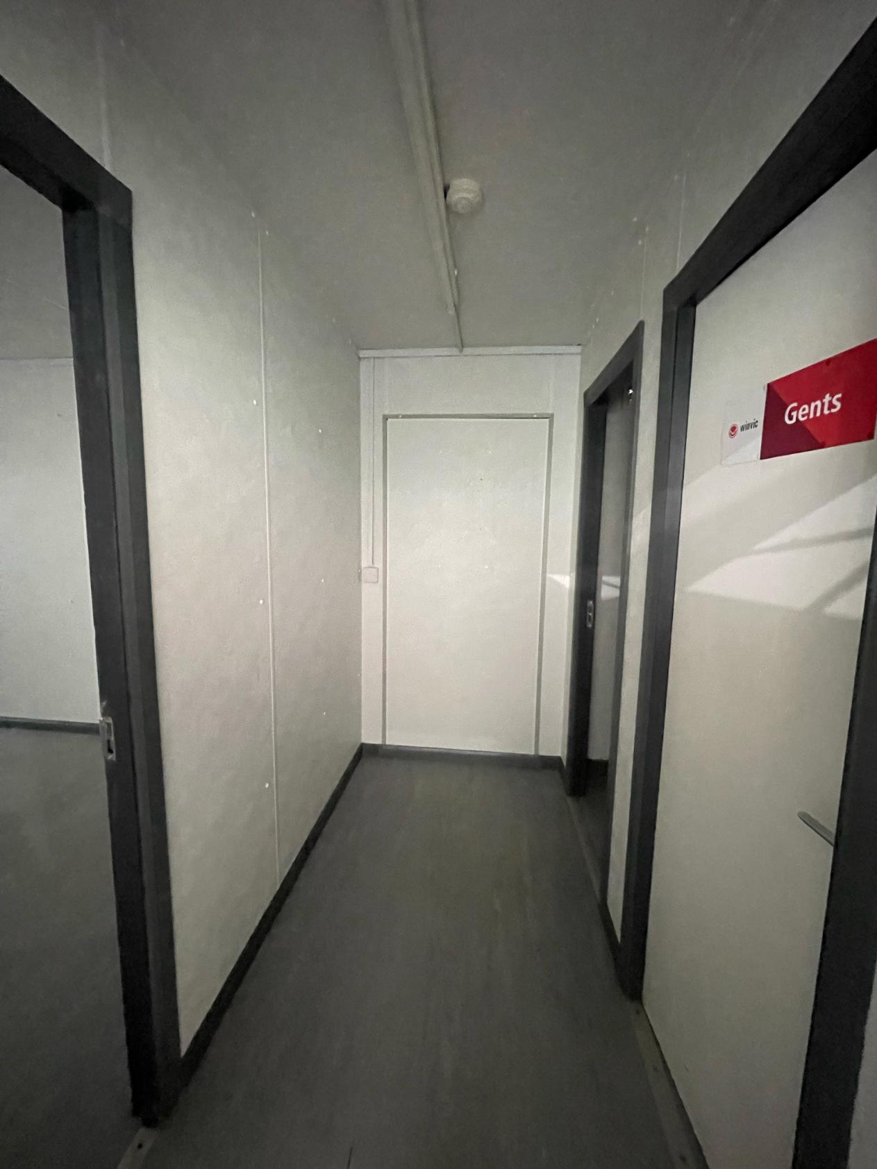
Hallway leading into:
Transport can be arranged please ask.


Location: Nationwide
Not Available for Hire
Call for an instant quote!
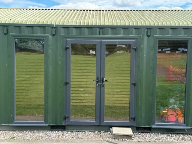
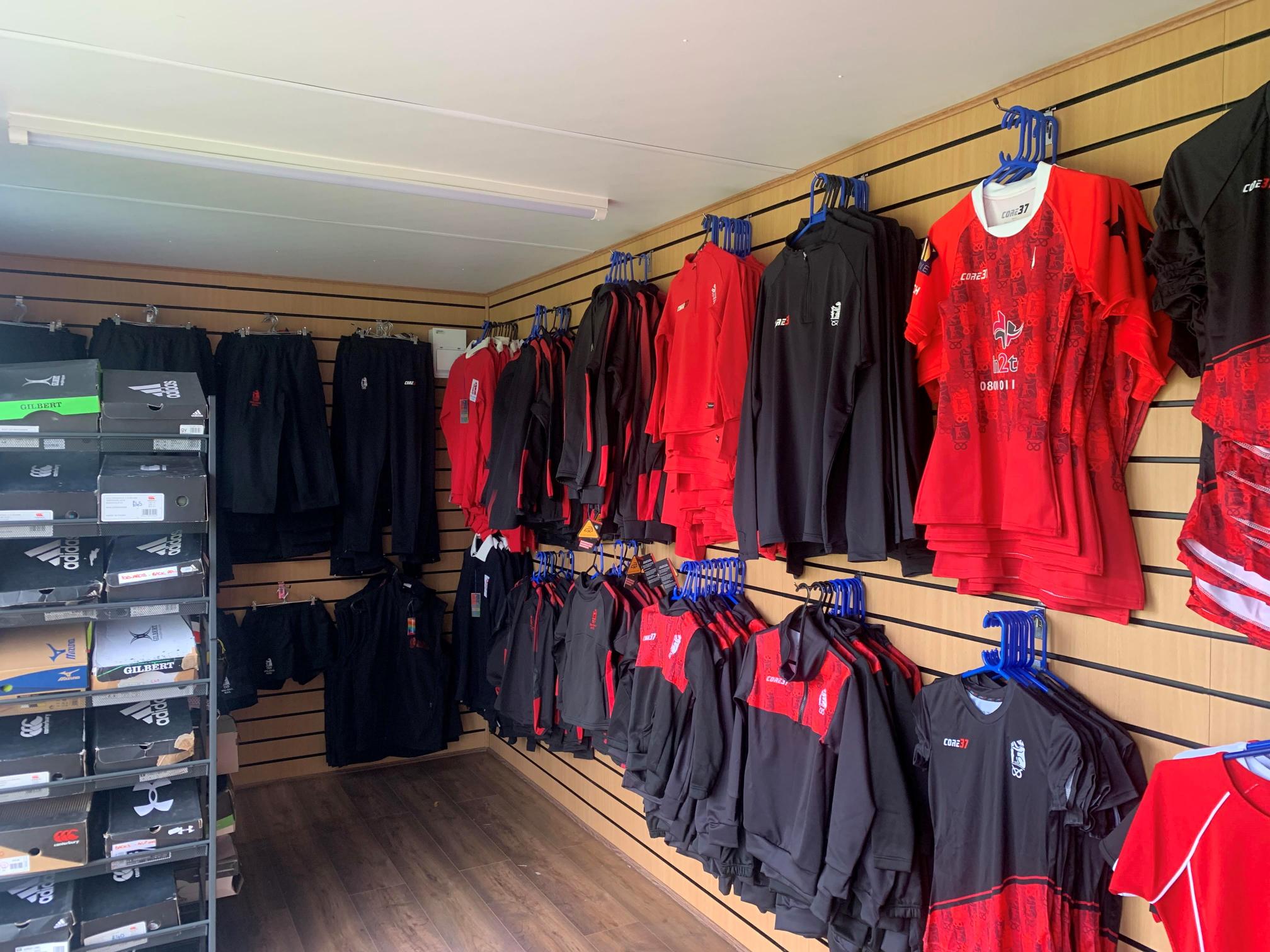
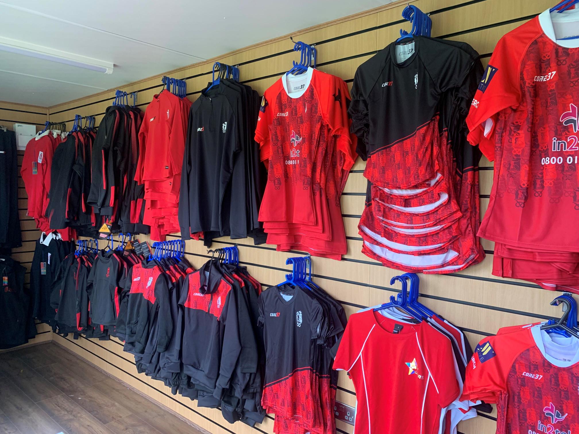
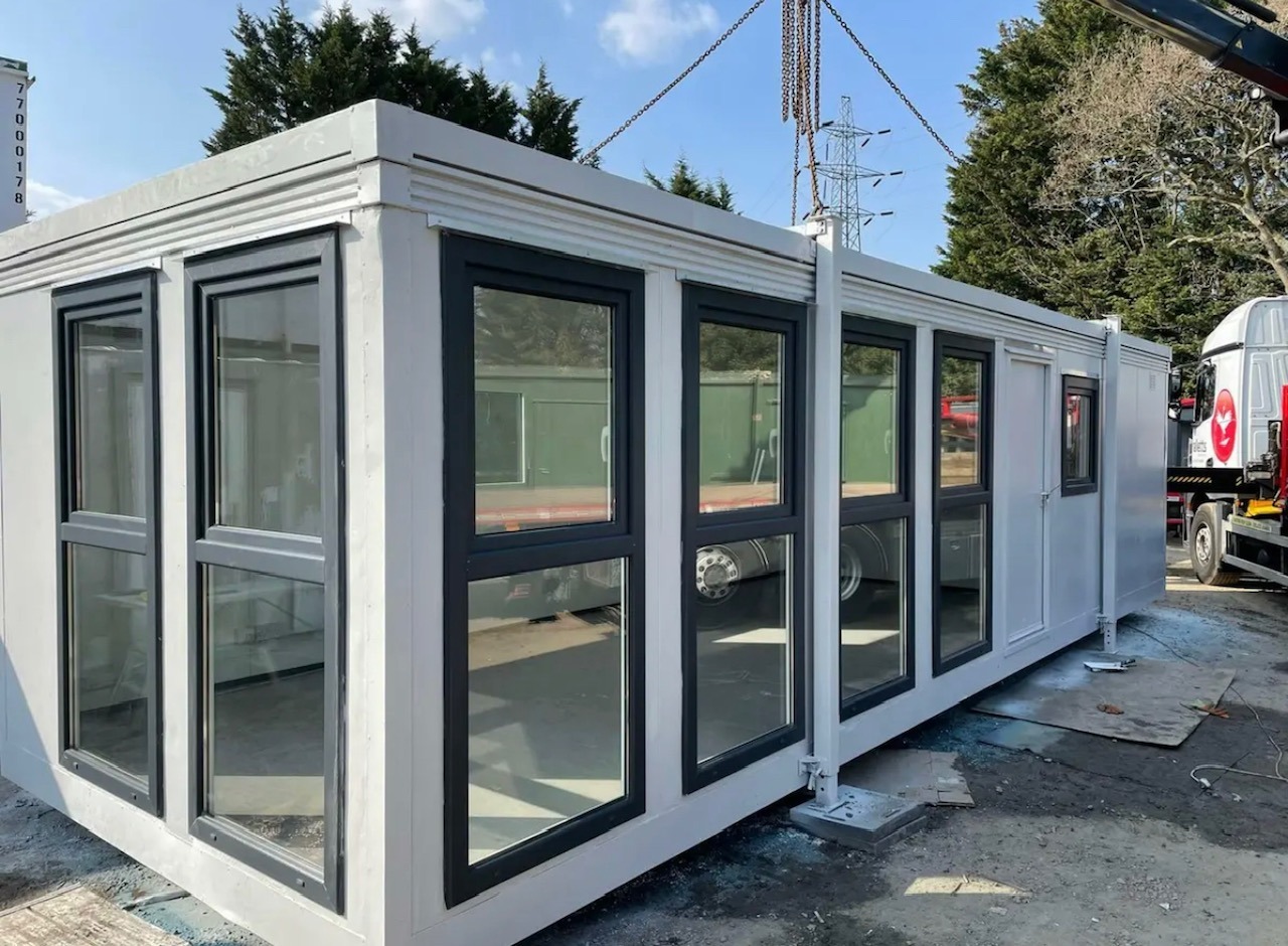
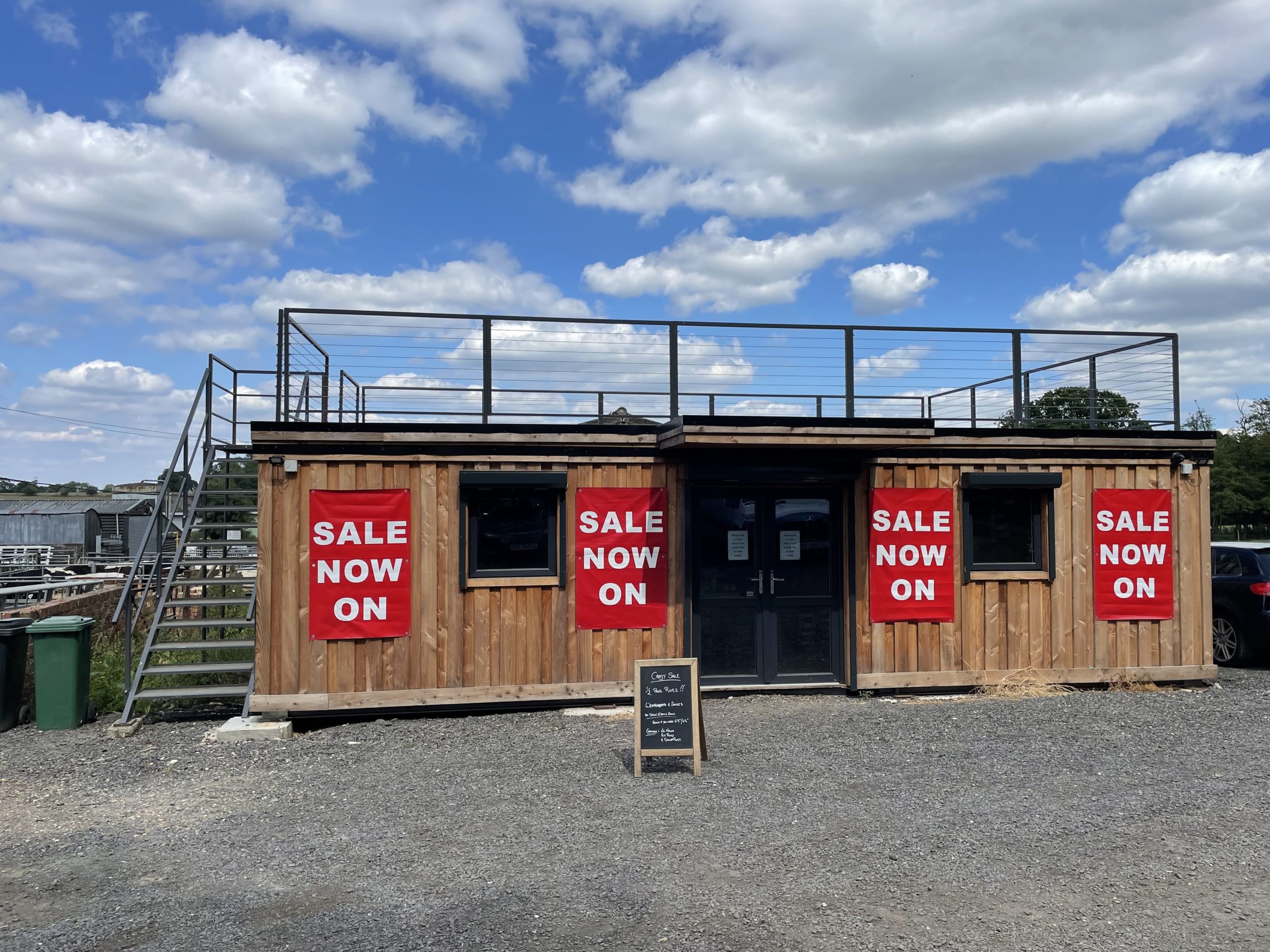
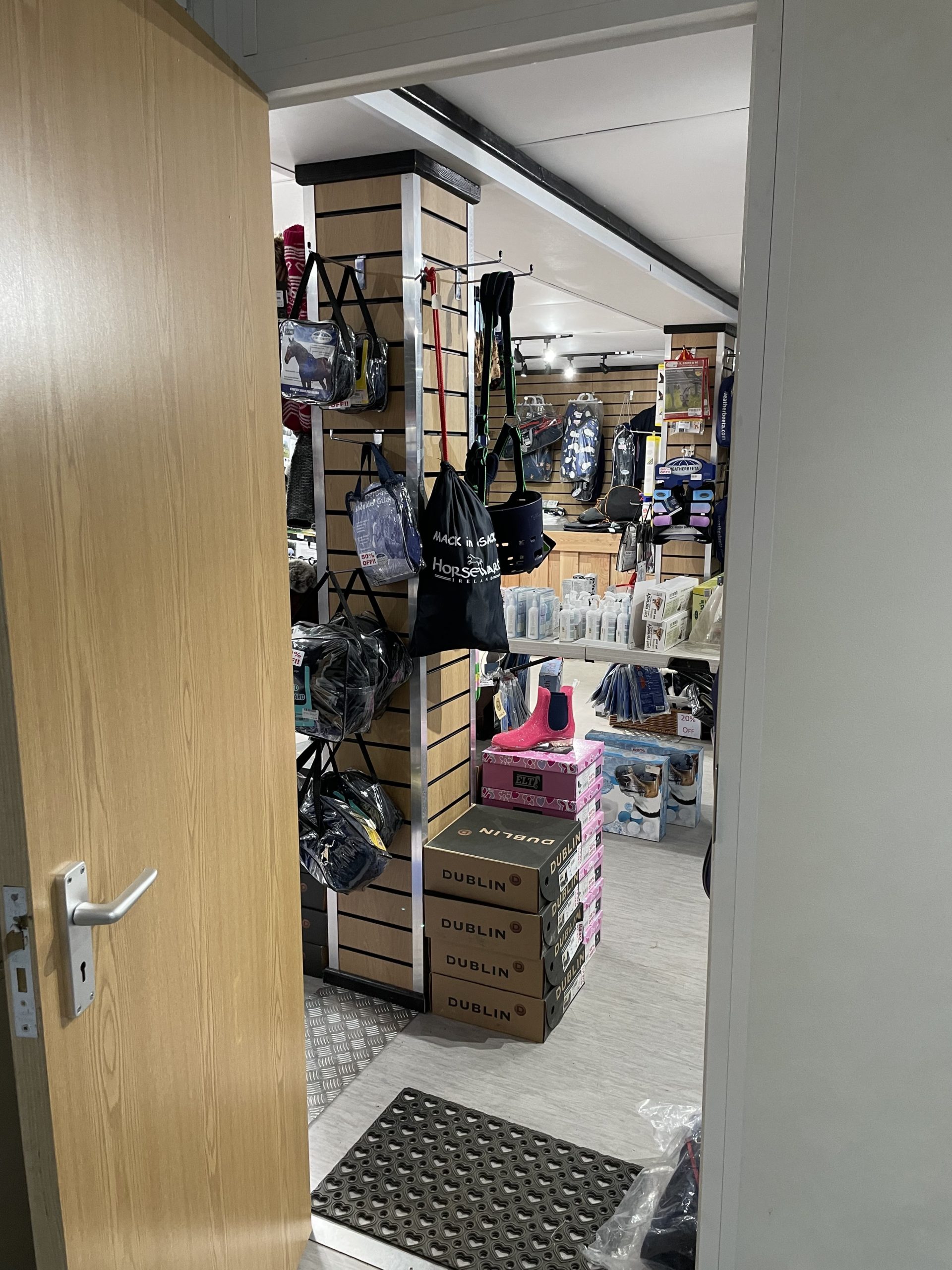
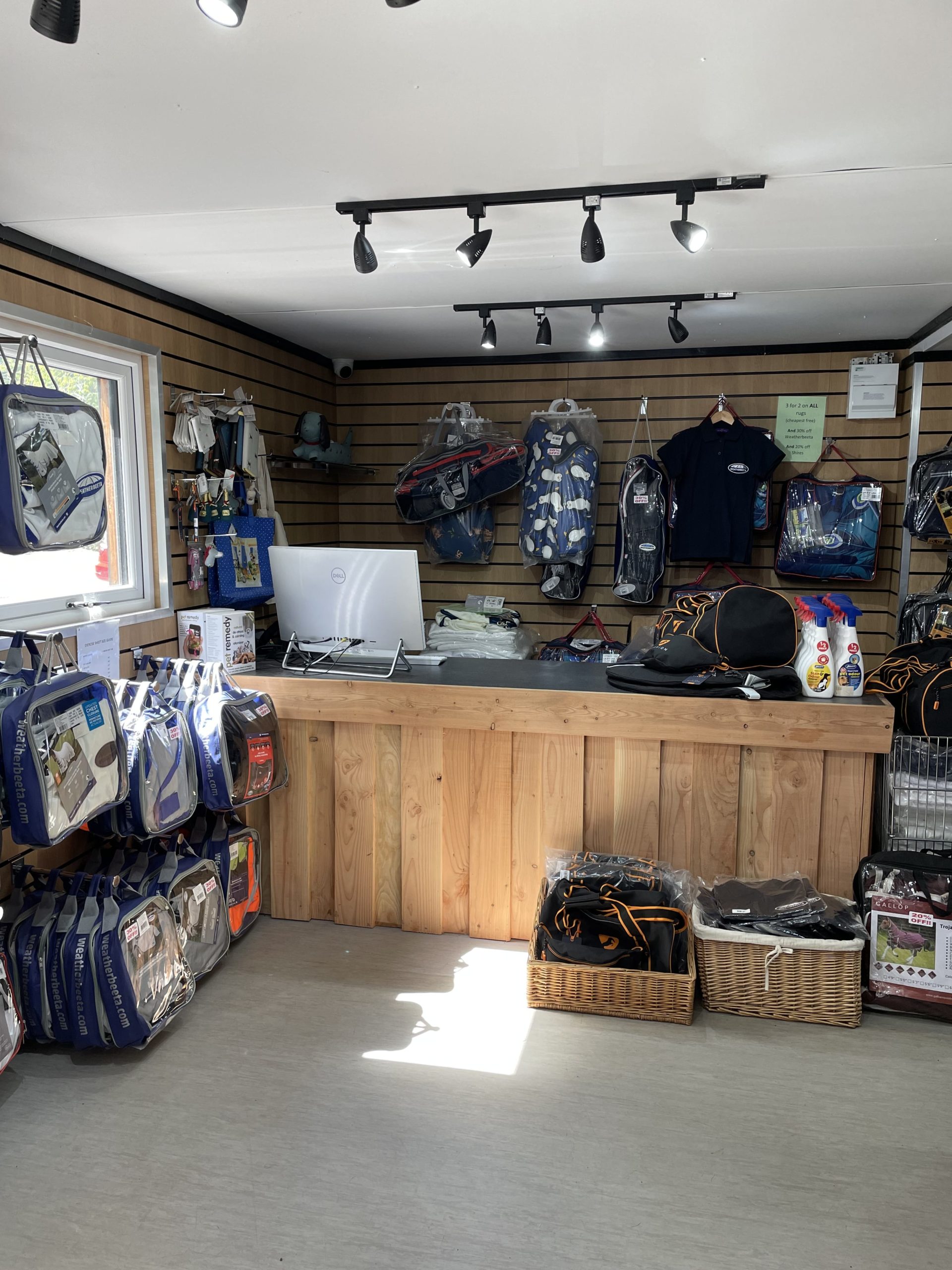
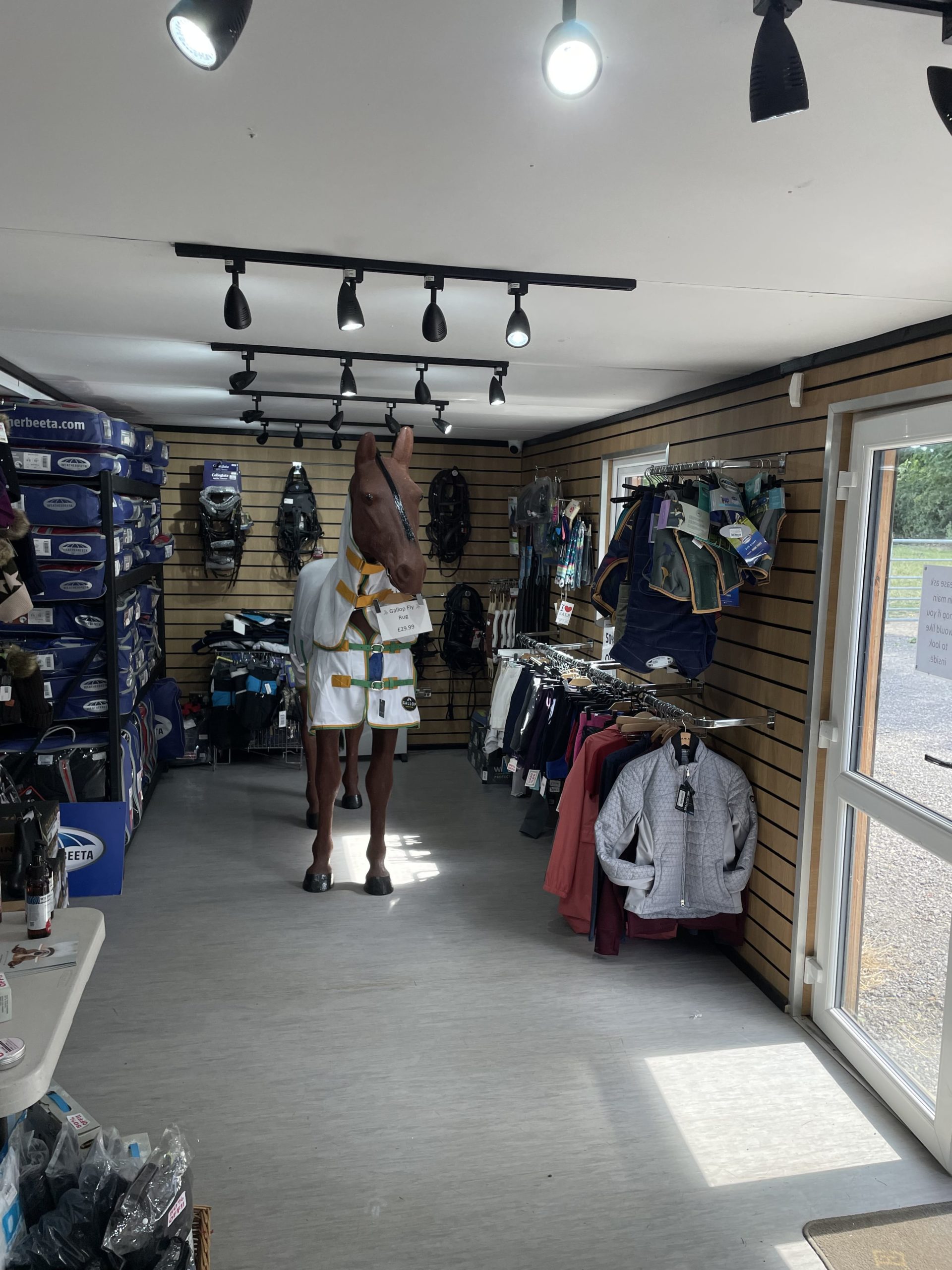
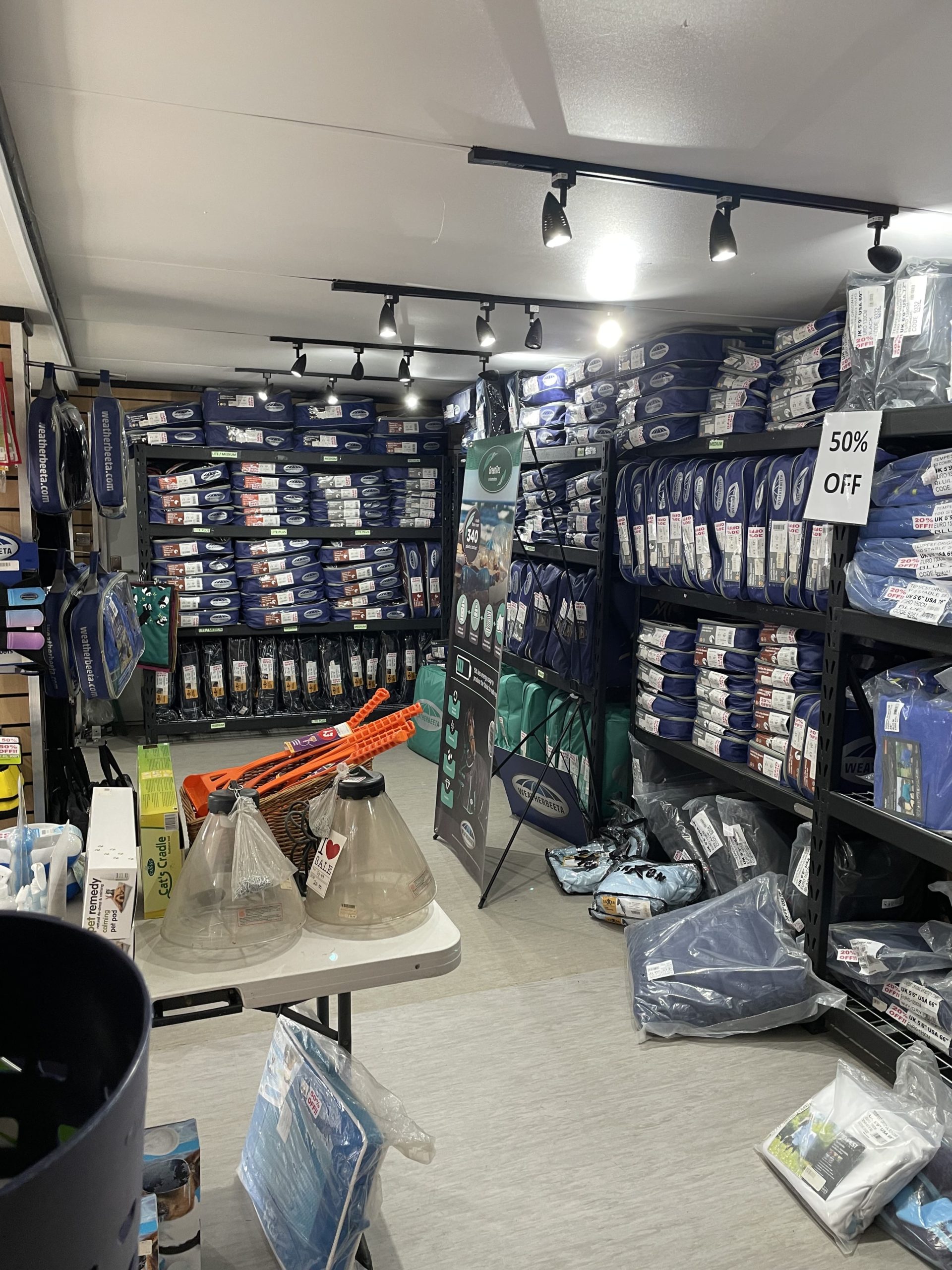
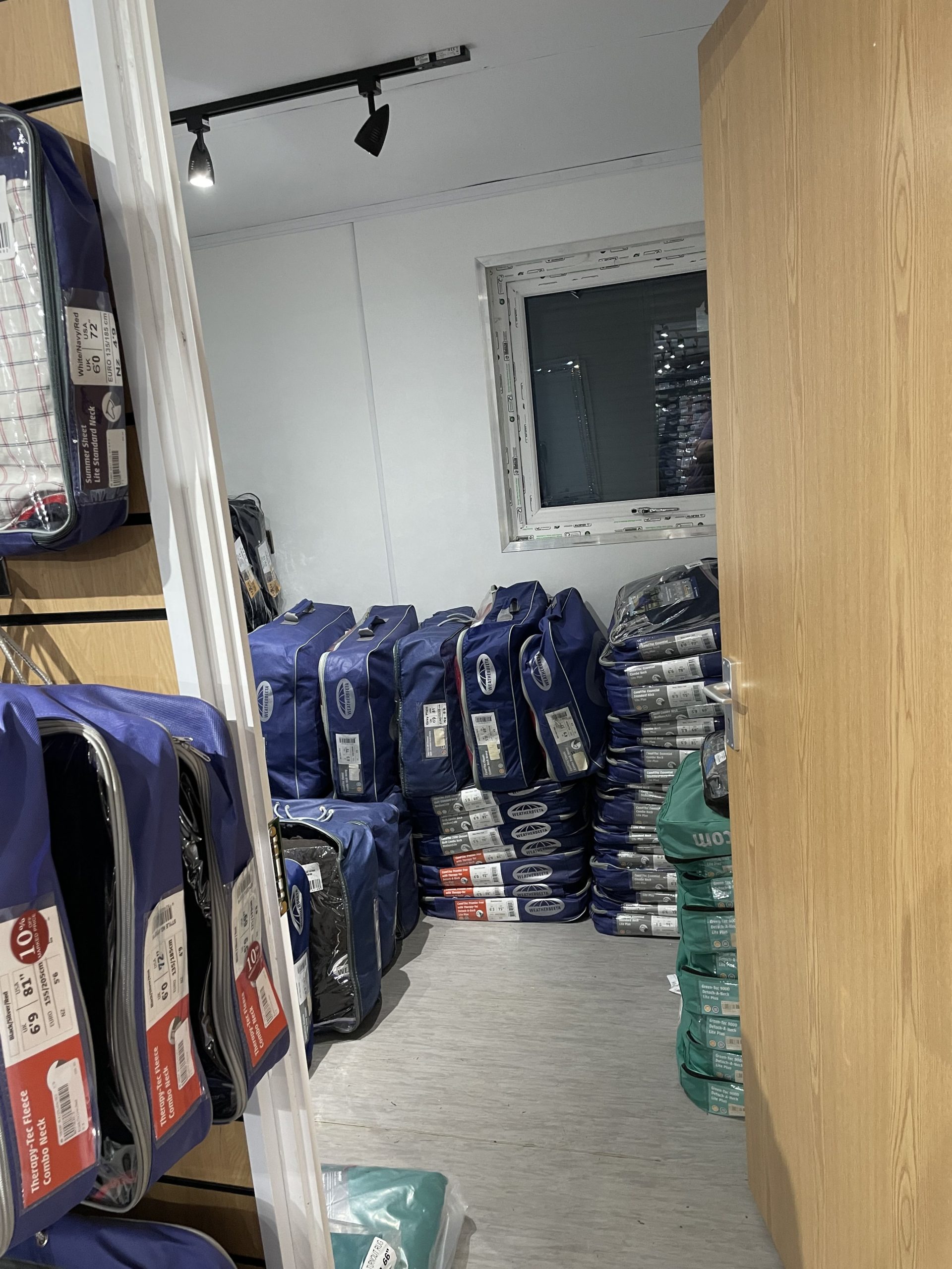
20ft x 8ft Container Conversion Retail Shop
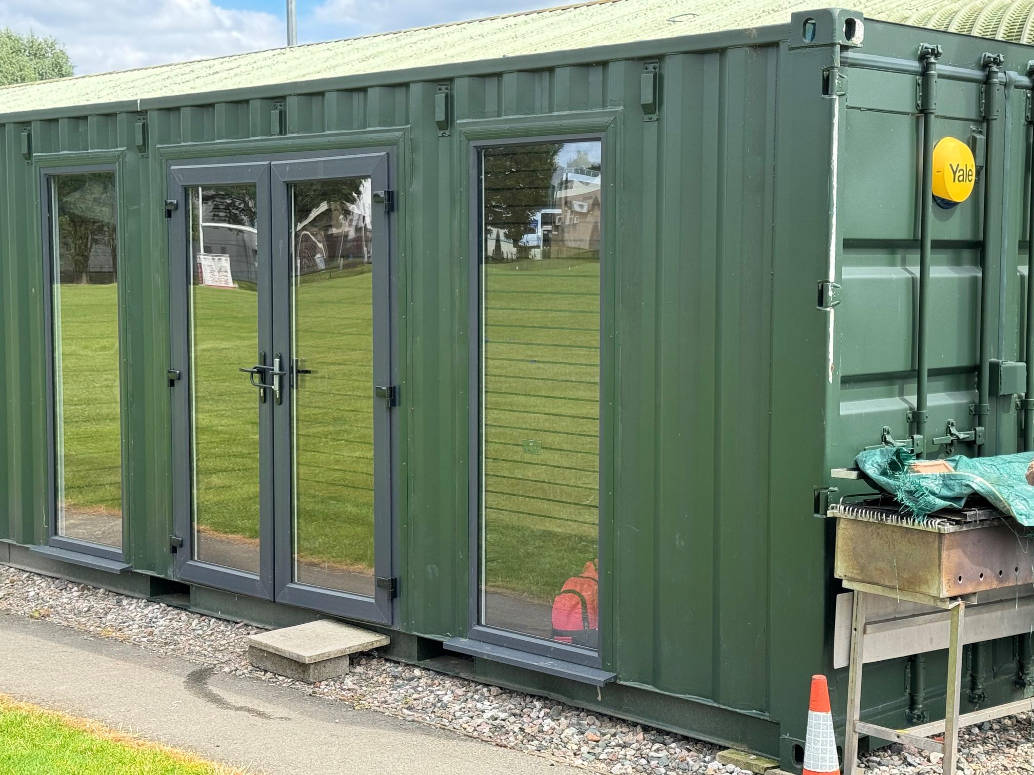
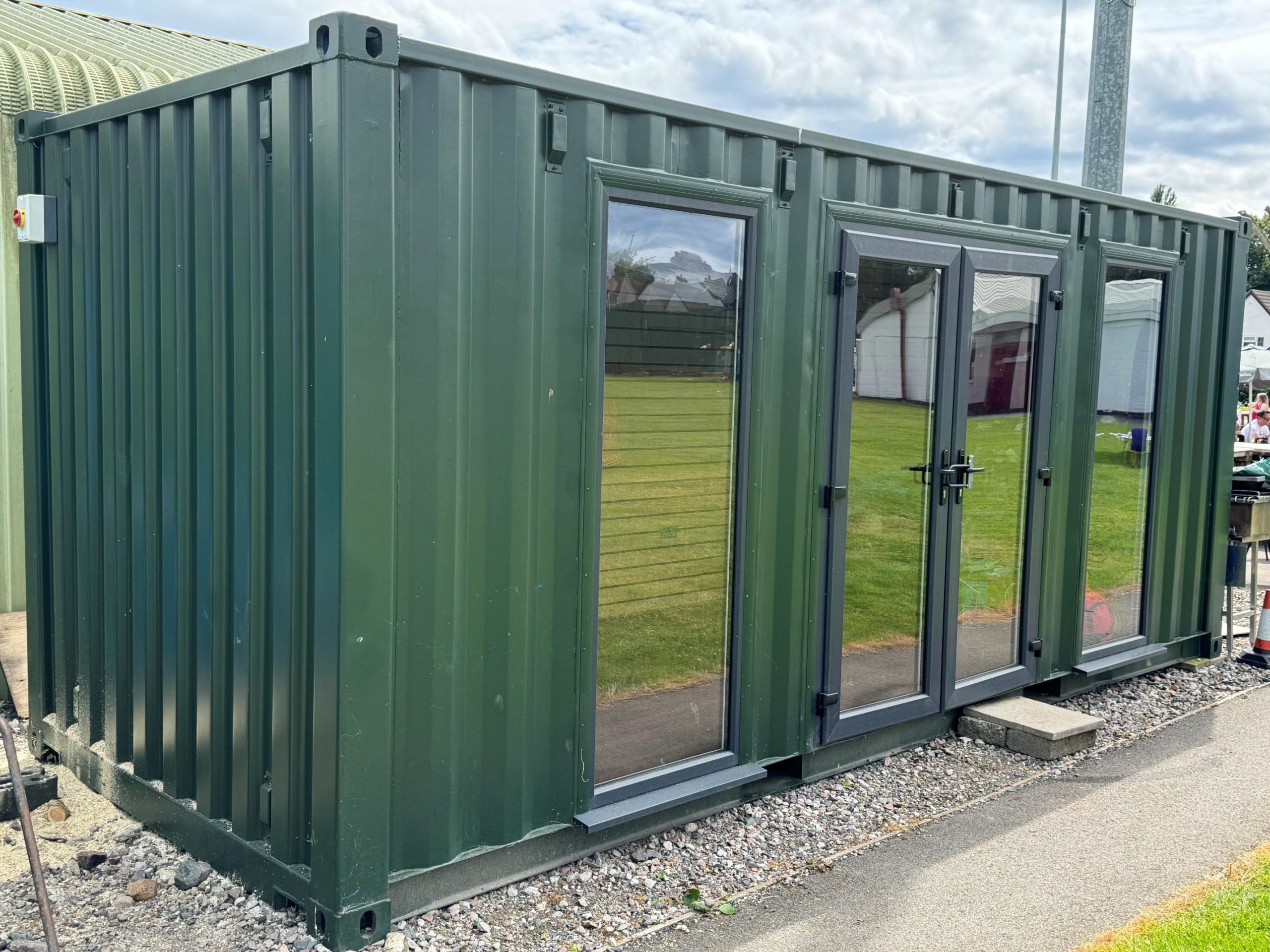
UPVC Double glazed Windows + French Doors
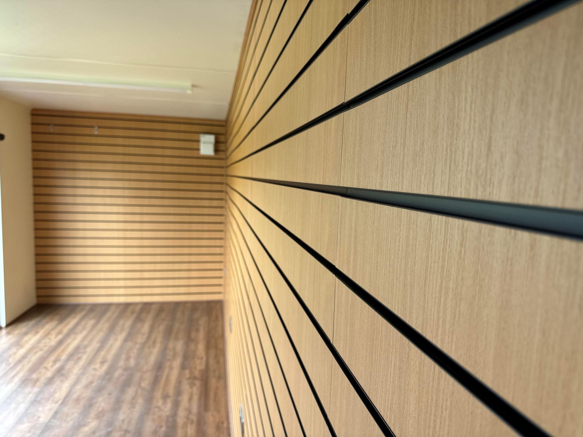
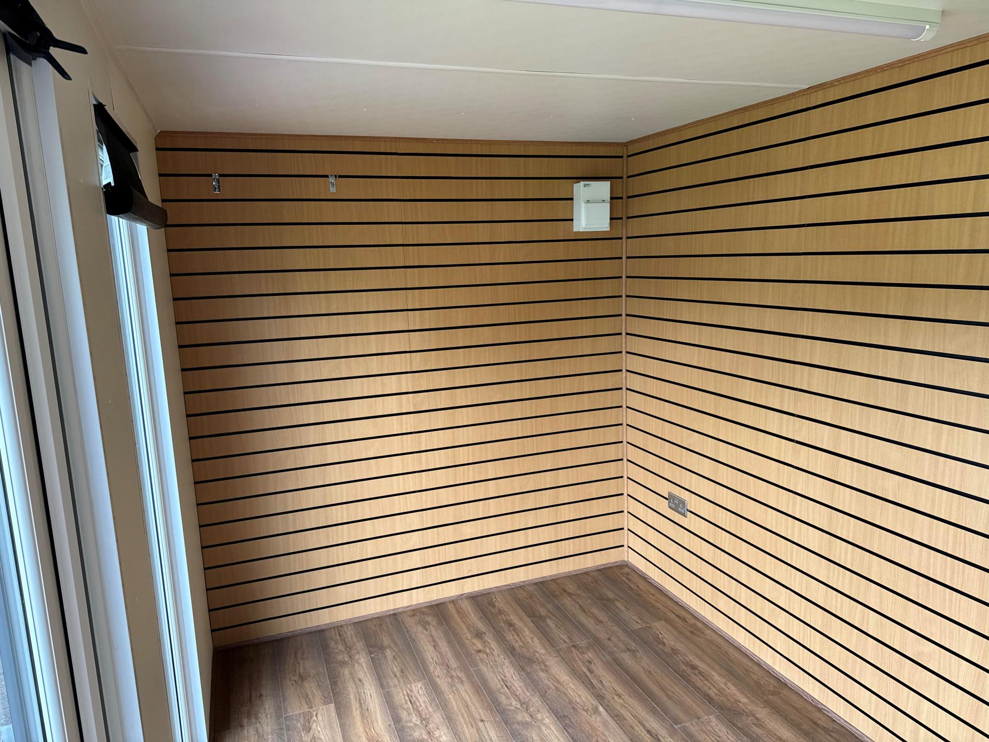
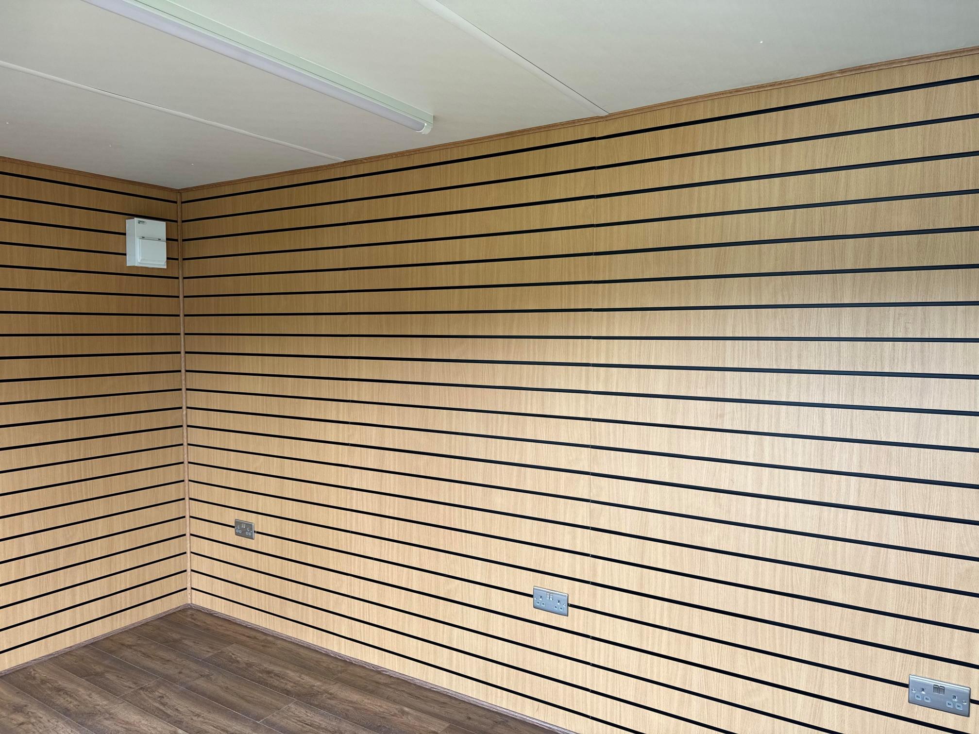
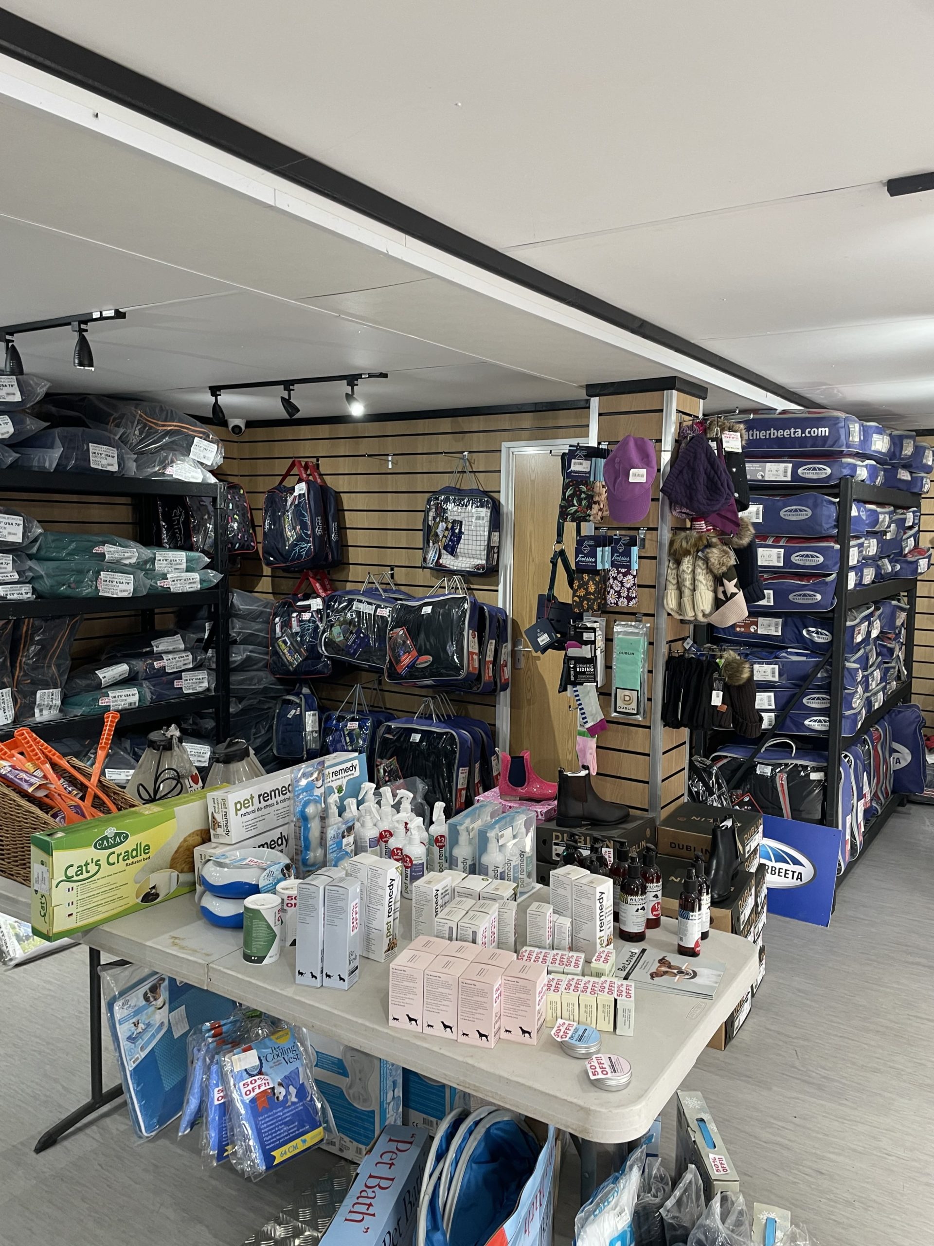
Slat Wall for retail fixings and Merchandise
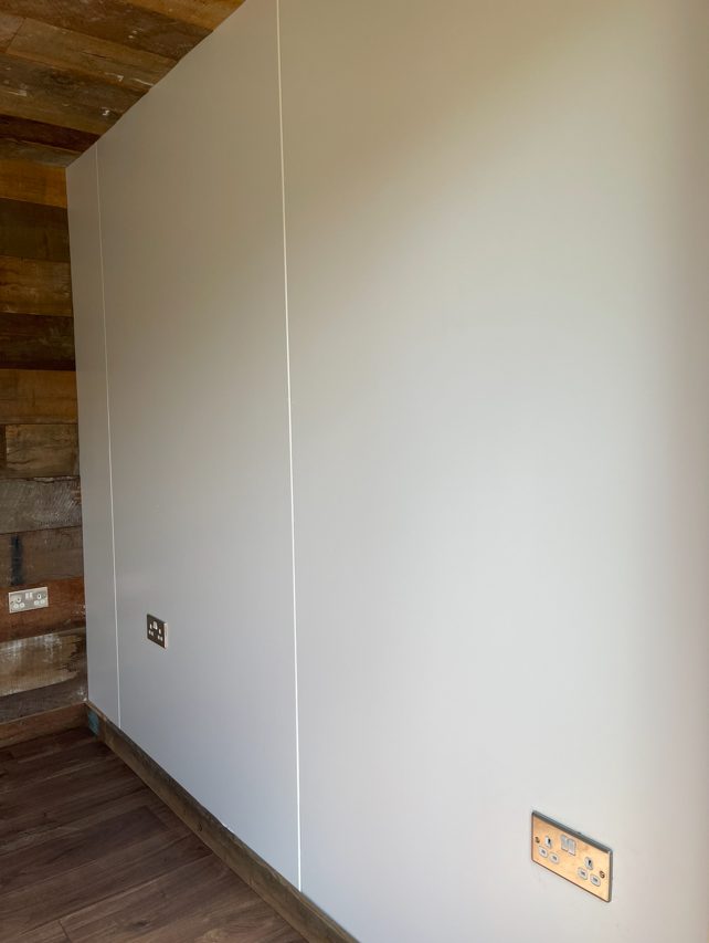
Electric Chrome Sockets, led lighting and heating.
Laminate Flooring
12 months Warranty
Maintenance call out package included
Less than 2 years old
Still in Brand New Condition


Fully refurbished
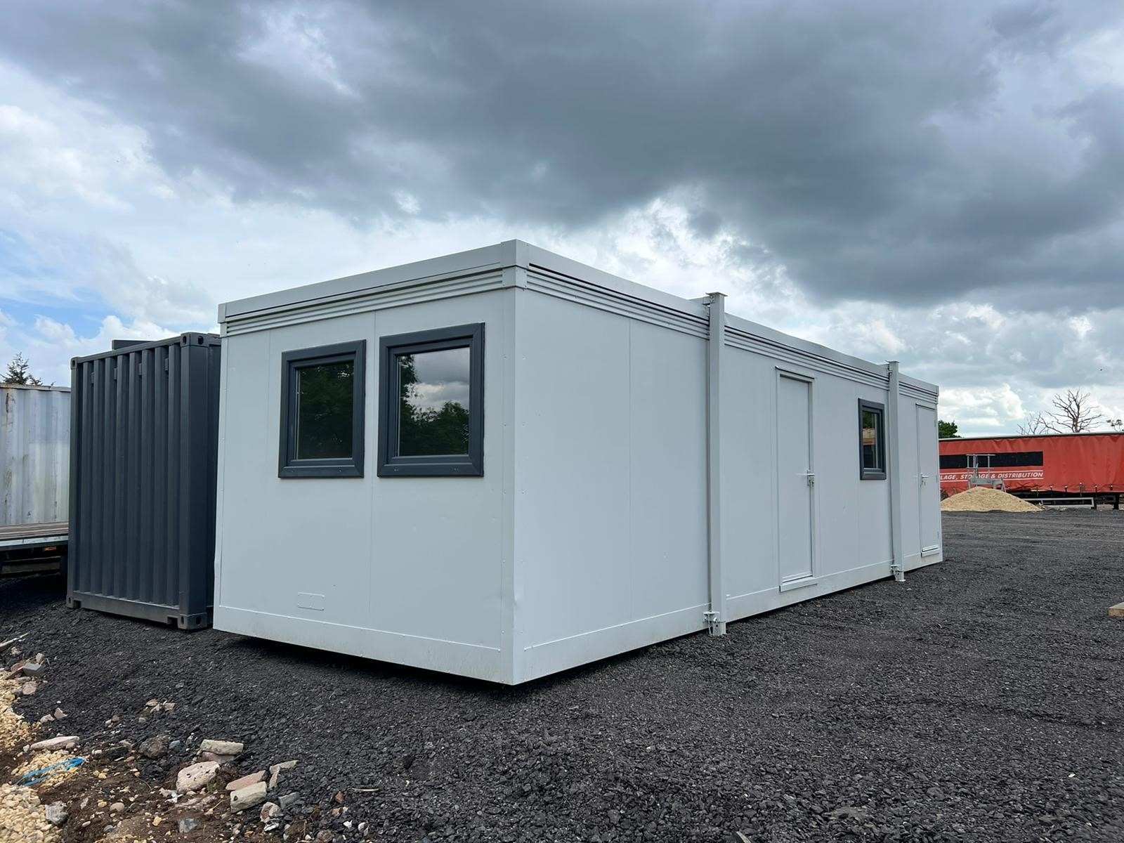
Colour light grey
Slate grey anthracite upvc double glazed windows


Location: Nationwide
+ VAT
Not Available for Hire
Call for an instant quote!
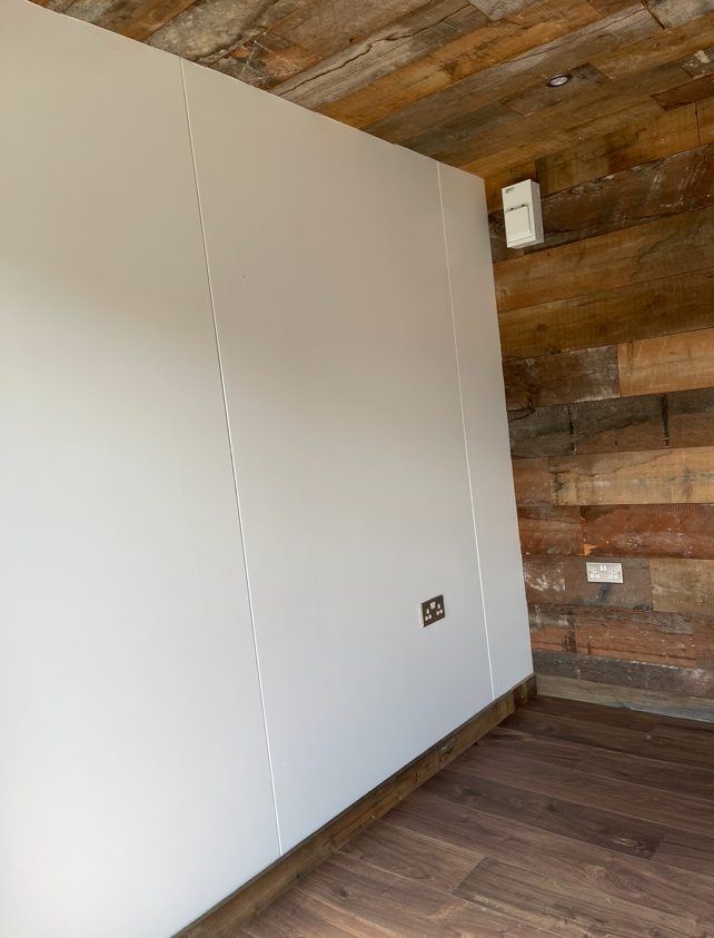
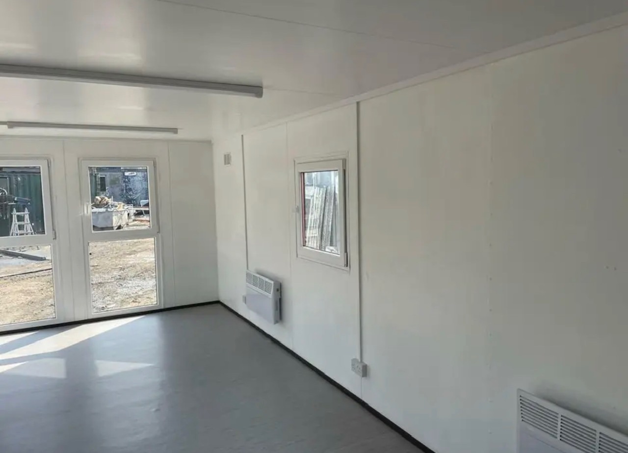
Fully Insulated with electric sockets, spot lighting, and heating
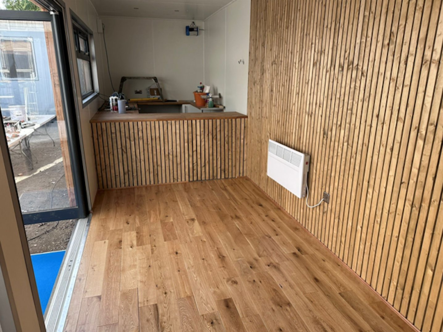
Wood Flooring
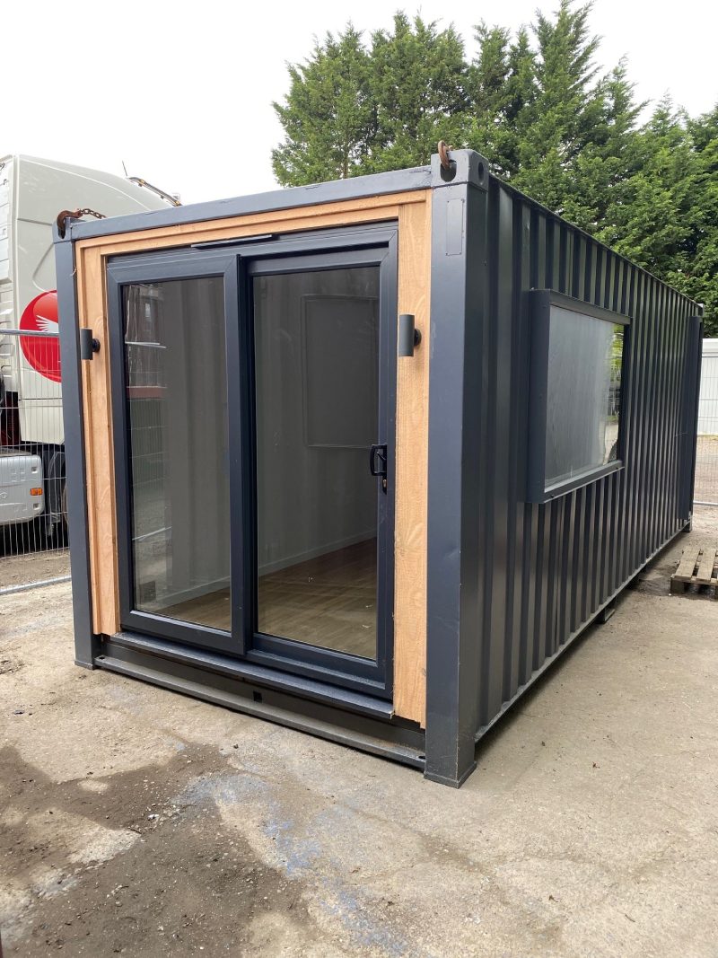
UPVC Sliding Door + Windows
Lead Time for build 6-8 weeks


Location: Nationwide
+ VAT
Not Available for Hire
Call for an instant quote!
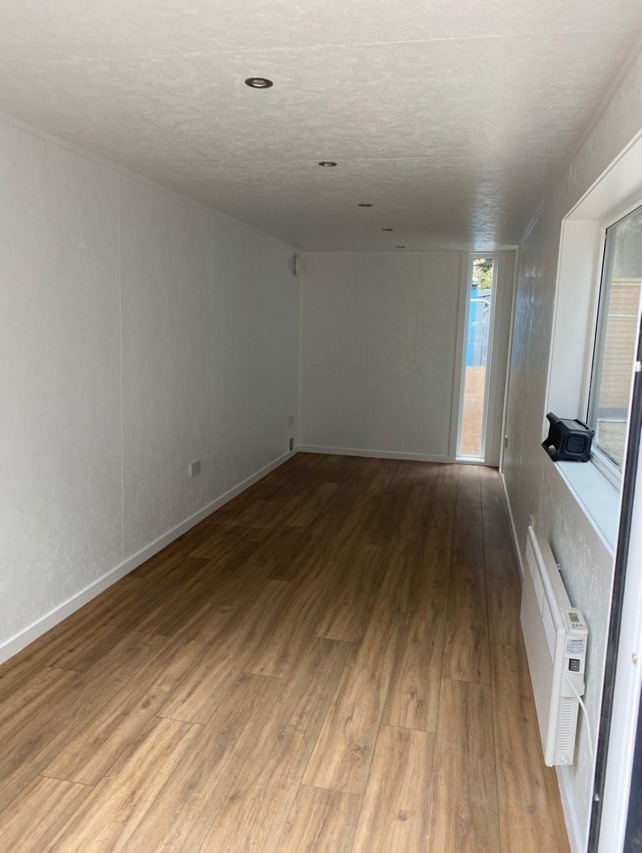
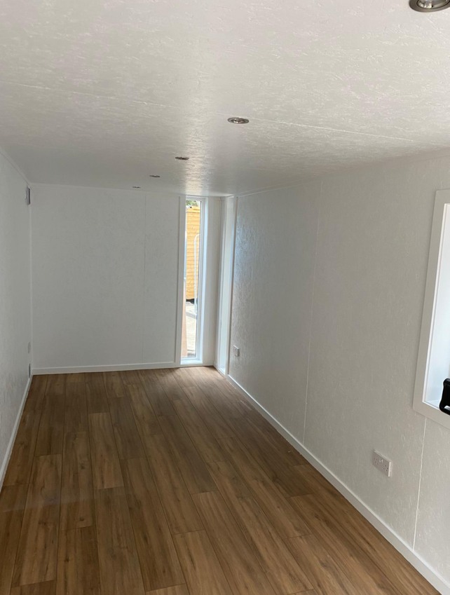
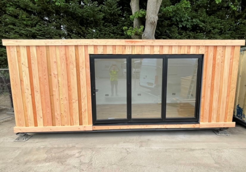
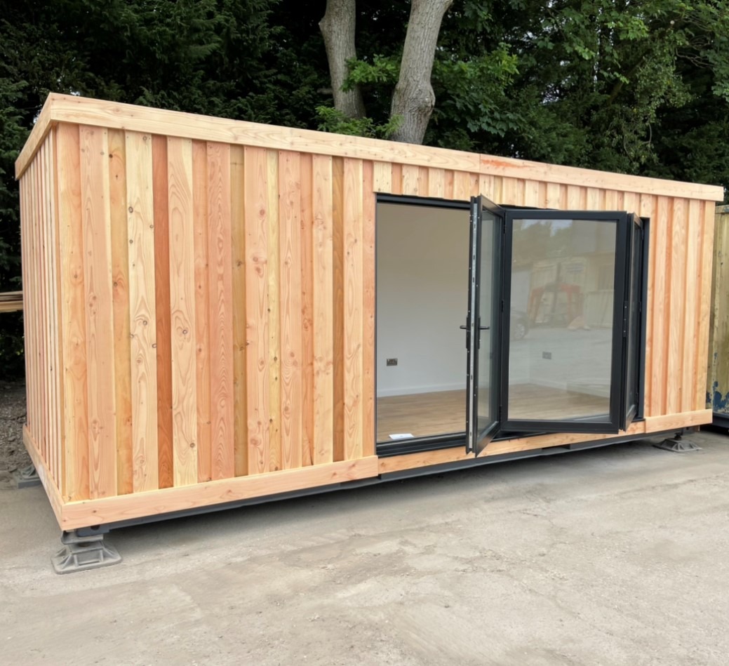
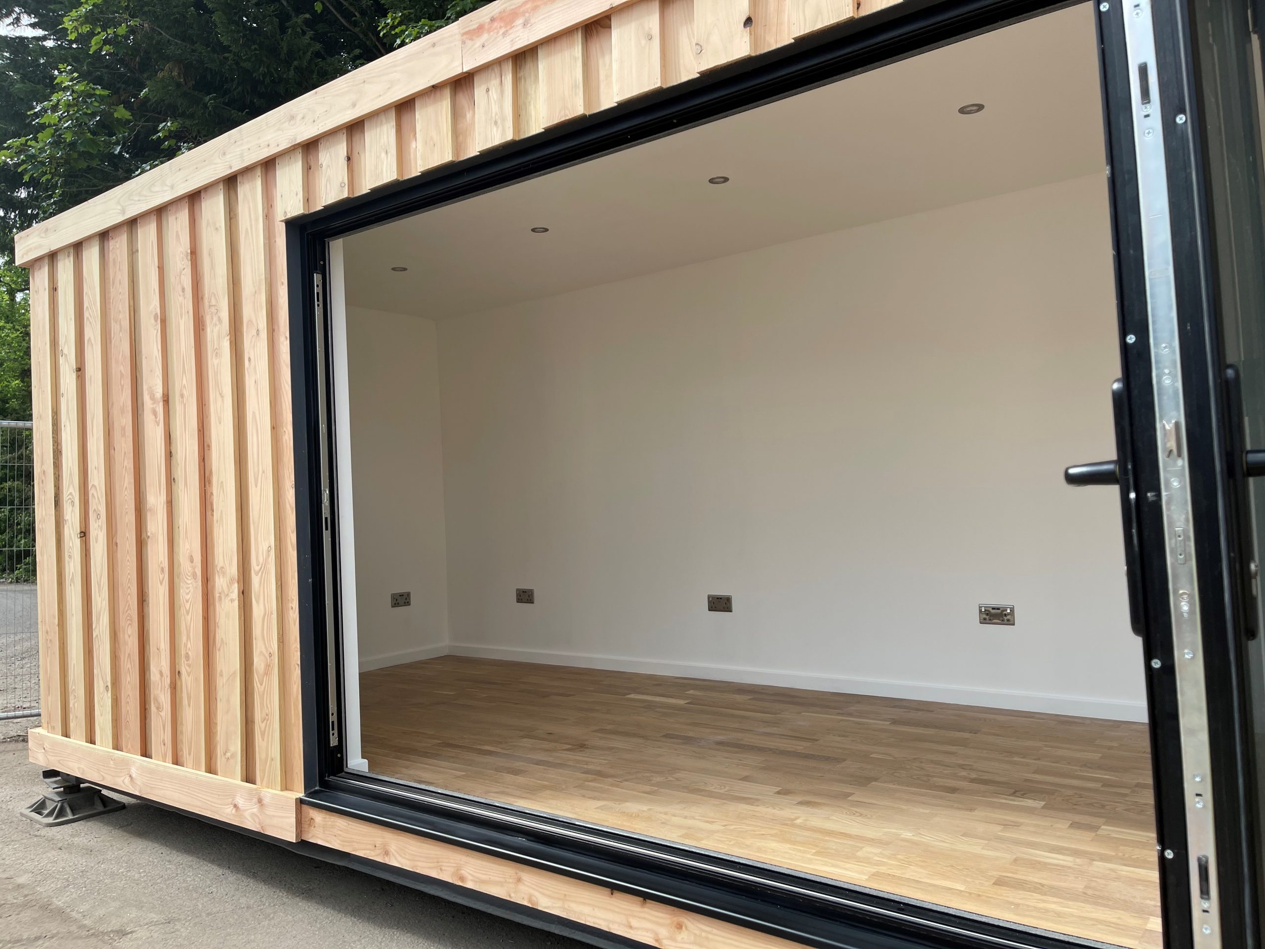
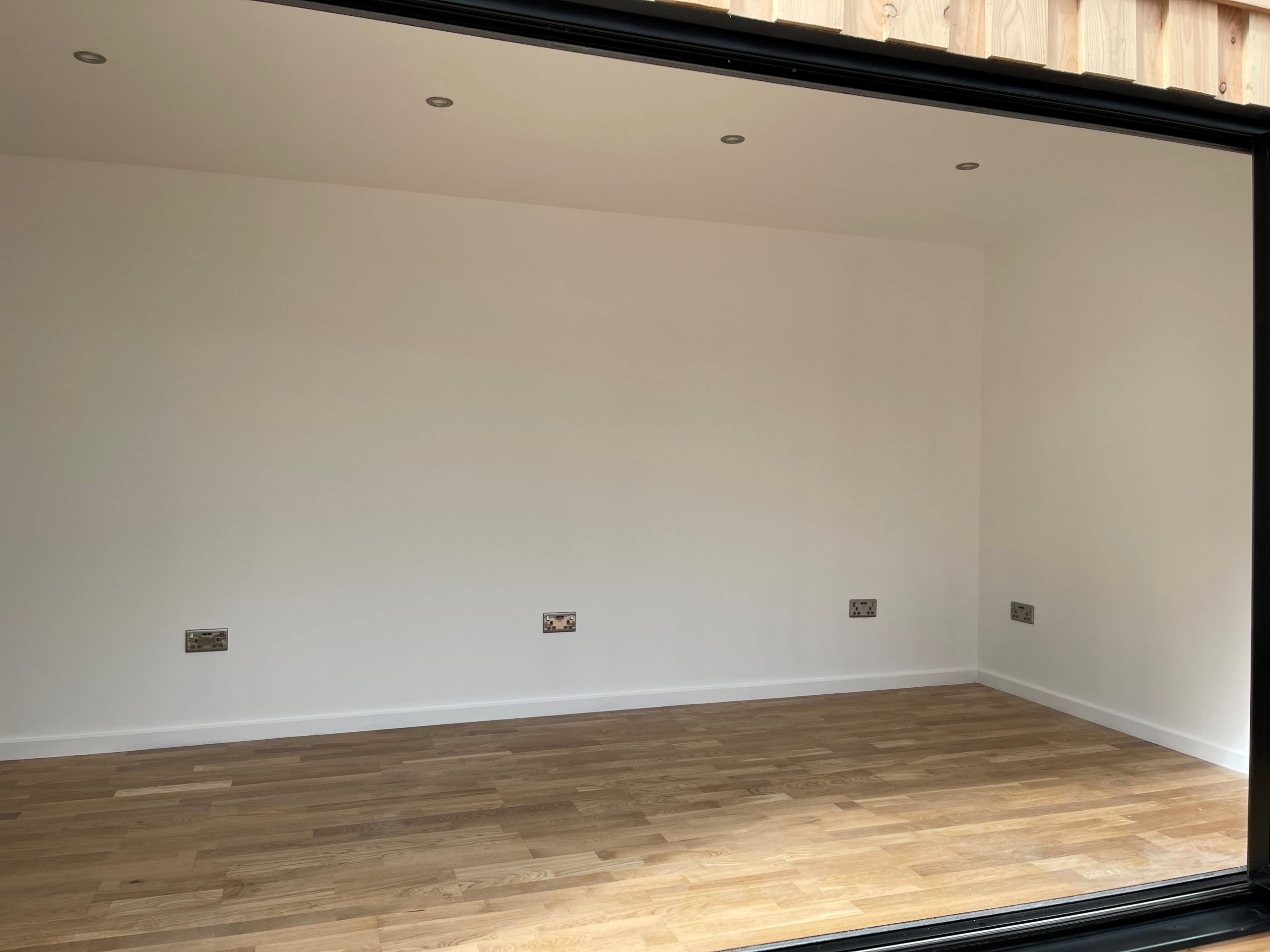
Fully Insulated with electric sockets, spot lighting, and heating
Wood Flooring
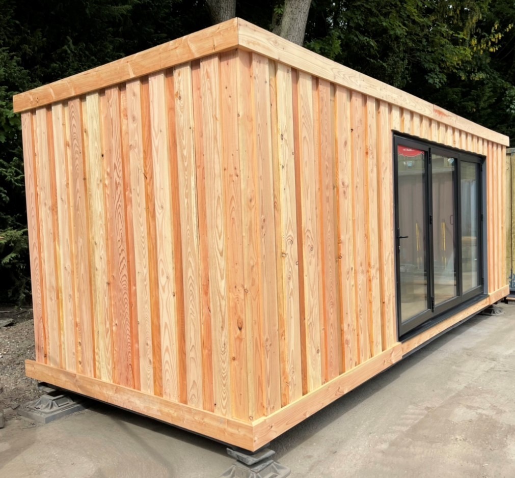
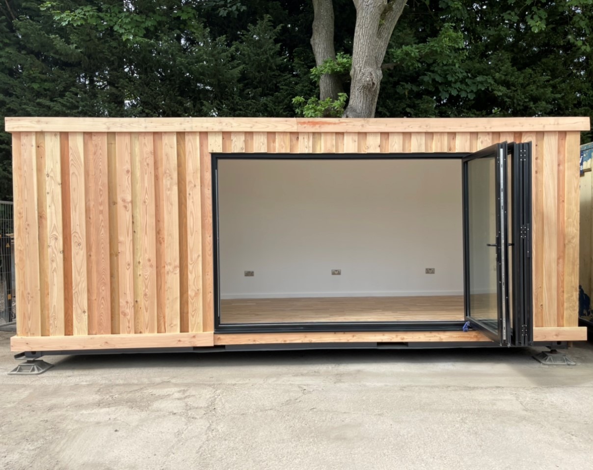
Aluminium Bi Fold Doors
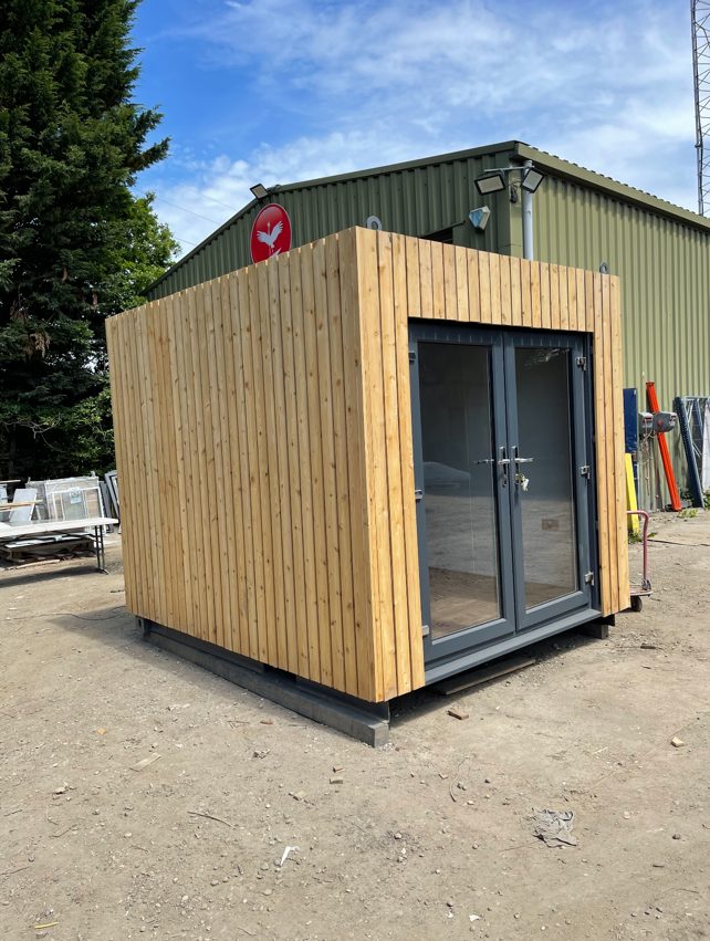
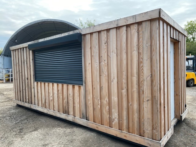
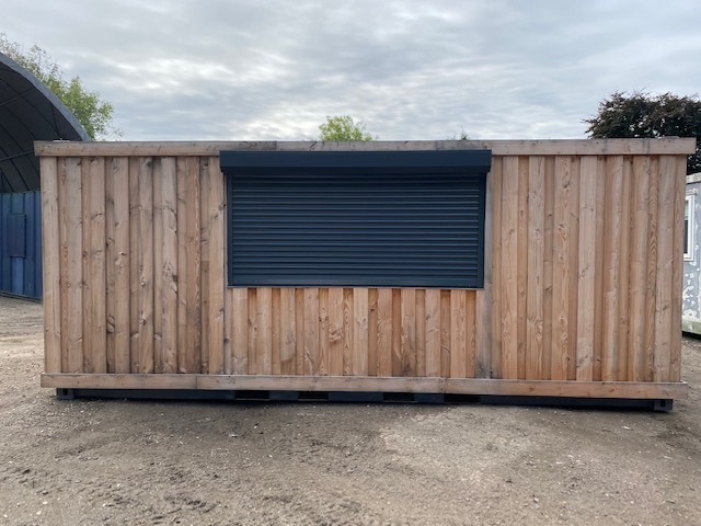
Fully wrapped in larch cladding
Lead Time for build 6-8 weeks


Location: Nationwide
+ VAT
Not Available for Hire
Call for an instant quote!
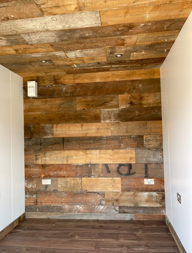
Fully Insulated with electric sockets, spot lighting, and heating
Wood Flooring
Feature Clad Wall and Ceiling
UPVC Double glazed French Doors
Fully wrapped in larch cladding
Lead Time for build 6-8 weeks


Location: Nationwide
EX VAT
Not Available for Hire
Call for an instant quote!


Location: Nationwide
EX VAT
Not Available for Hire
Call for an instant quote!


Location: Nationwide
EX VAT
Not Available for Hire
Call for an instant quote!


Location: Nationwide
EX VAT
Not Available for Hire
Call for an instant quote!


Location: Nationwide
EX VAT
Not Available for Hire
Call for an instant quote!

Location: Nationwide
EX VAT
Not Available for Hire
Call for an instant quote!


Location: Nationwide
EX VAT
Not Available for Hire
Call for an instant quote!


Location: Nationwide
EX VAT
Not Available for Hire
Call for an instant quote!


Location: Nationwide
EX VAT
Not Available for Hire
Call for an instant quote!


Location: Nationwide
EX VAT
Not Available for Hire
Call for an instant quote!


Location: Nationwide
EX VAT
Not Available for Hire
Call for an instant quote!


Location: Nationwide
EX VAT
Not Available for Hire
Call for an instant quote!


Location: Nationwide
EX VAT
Not Available for Hire
Call for an instant quote!


Location: Nationwide
EX VAT
Not Available for Hire
Call for an instant quote!


Location: Nationwide
EX VAT
Not Available for Hire
Call for an instant quote!


Location: Nationwide
EX VAT
Not Available for Hire
Call for an instant quote!
10ftx8ft – £5950 + Vat / 16ftx8ft – £7950 + Vat / 20ftx8ft – £9000 + Vat / 24ftx8ft – £12000 + Vat / 30ftx8ft – £13500 + Vat


Location: Nationwide
EX VAT
Not Available for Hire
Call for an instant quote!


Location: Nationwide
EX VAT
Not Available for Hire
Call for an instant quote!


Location: Nationwide
EX VAT
Not Available for Hire
Call for an instant quote!

Location: Nationwide
Quantity: ∞
EX VAT
Not Available for Hire
Call for an instant quote!
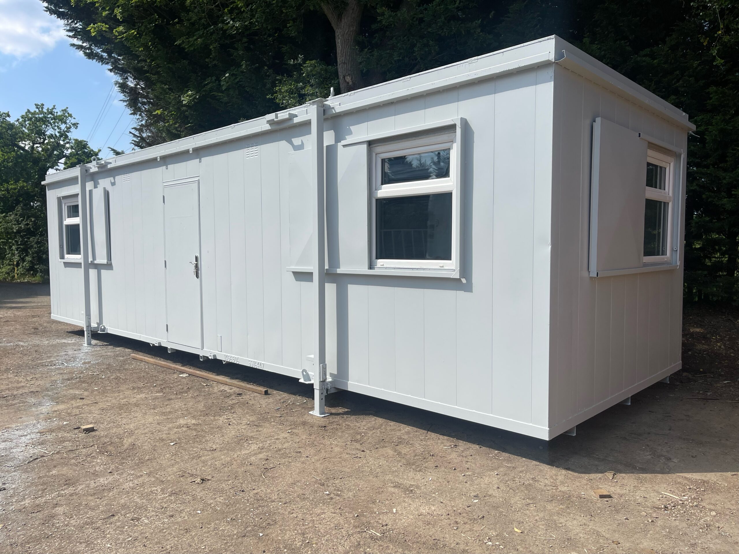
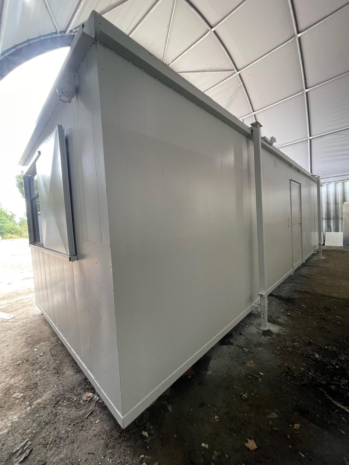
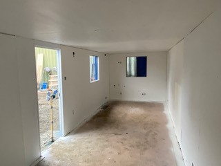
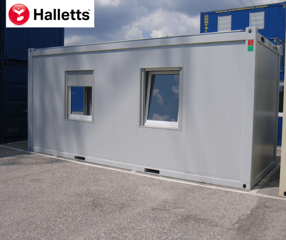
• Reinforced doors and windows with secure locking
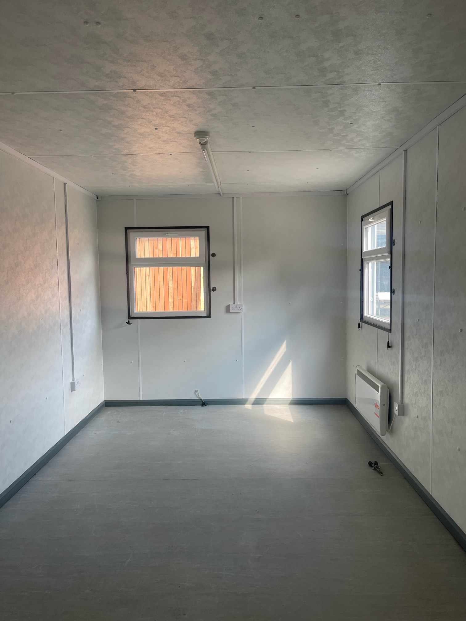
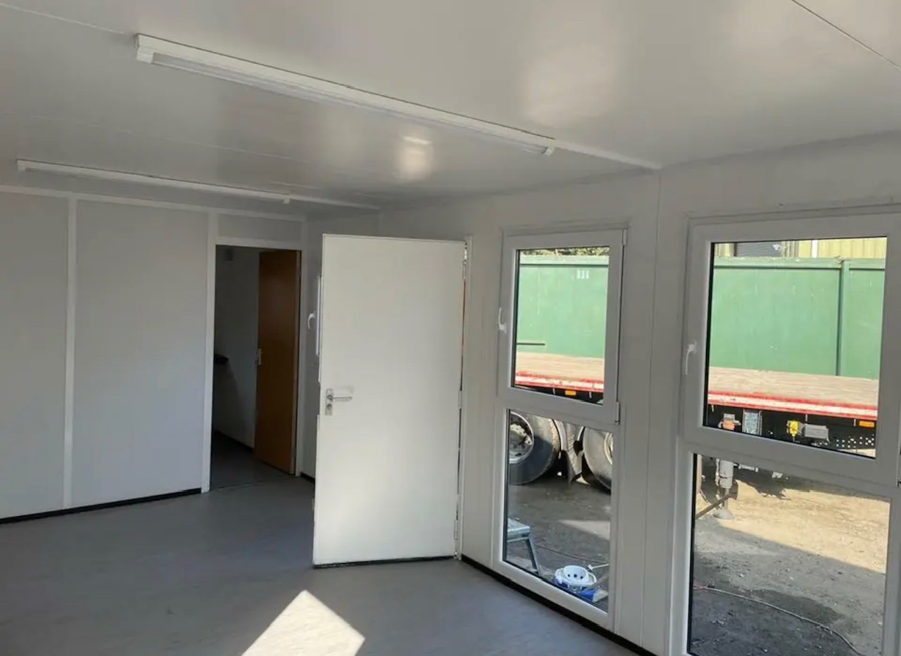
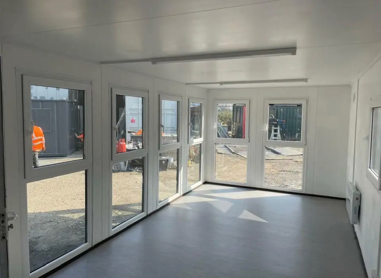
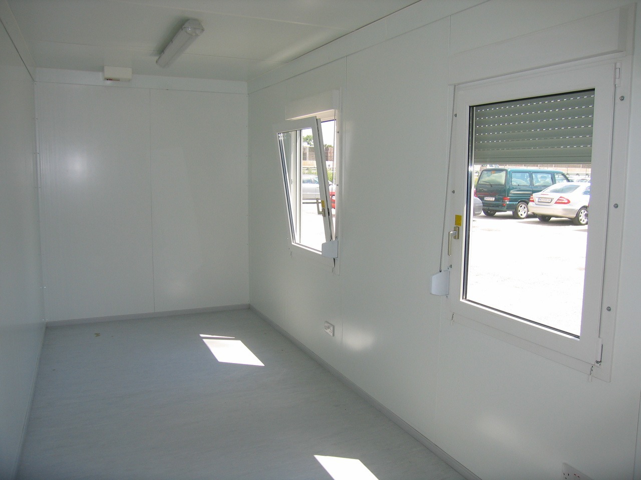
• Open plan with electric sockets and lighting
• Ral Code Colour of choice
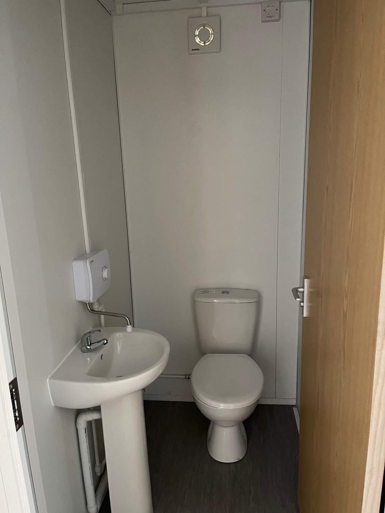
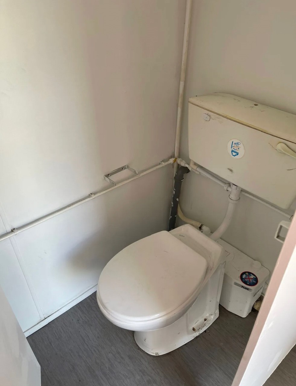
• Any Extras available : Canteen, Partitions, Toilets.


Location: Nationwide
EX VAT
Not Available for Hire
Call for an instant quote!
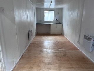
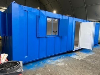
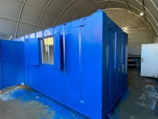
• Reinforced doors and windows with secure locking
• Open plan with electric sockets and lighting
• Ral Code Colour of choice
• Any Extras available : Canteen, Partitions, Toilets.

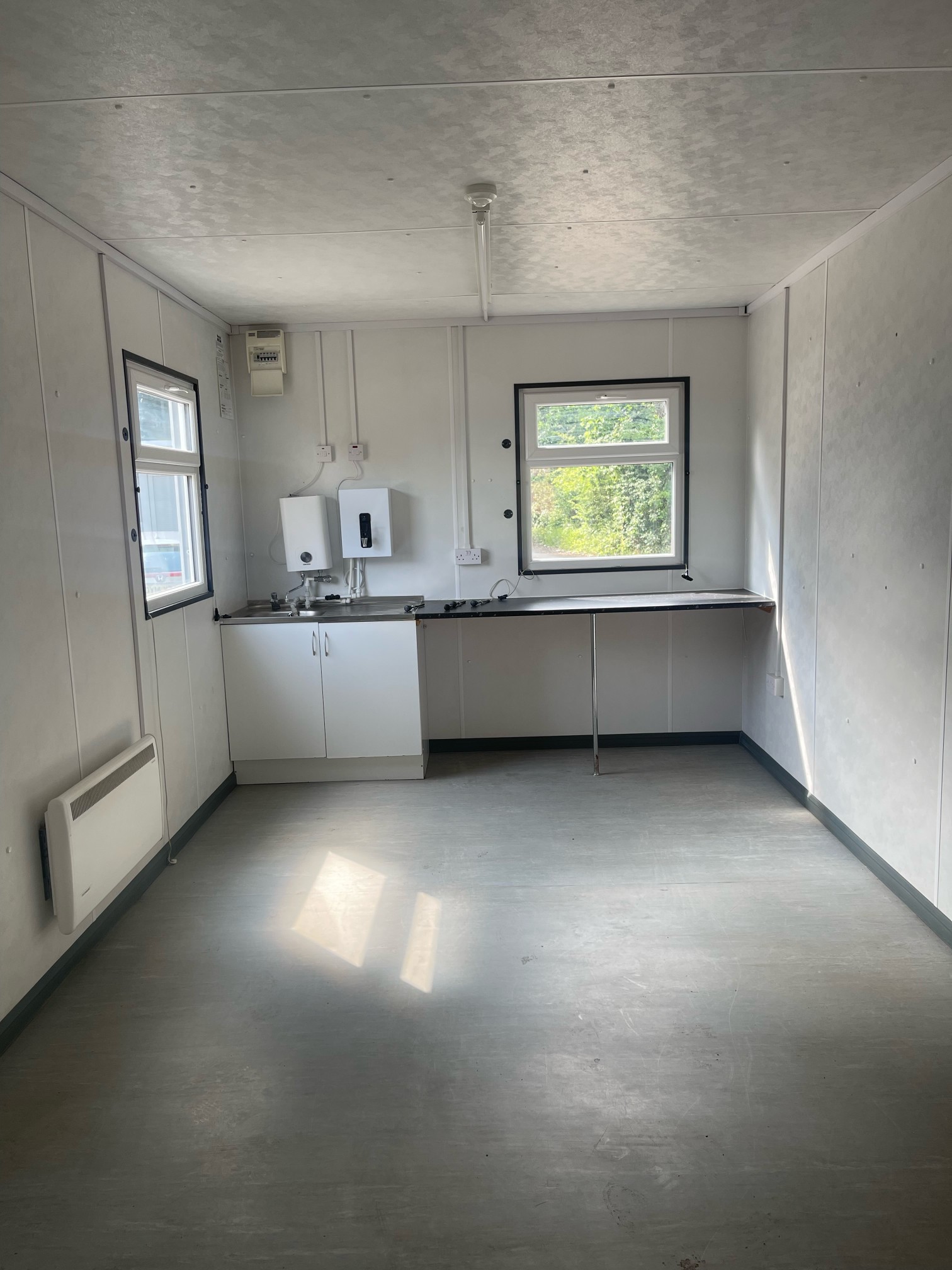
• Reinforced doors with secure locking
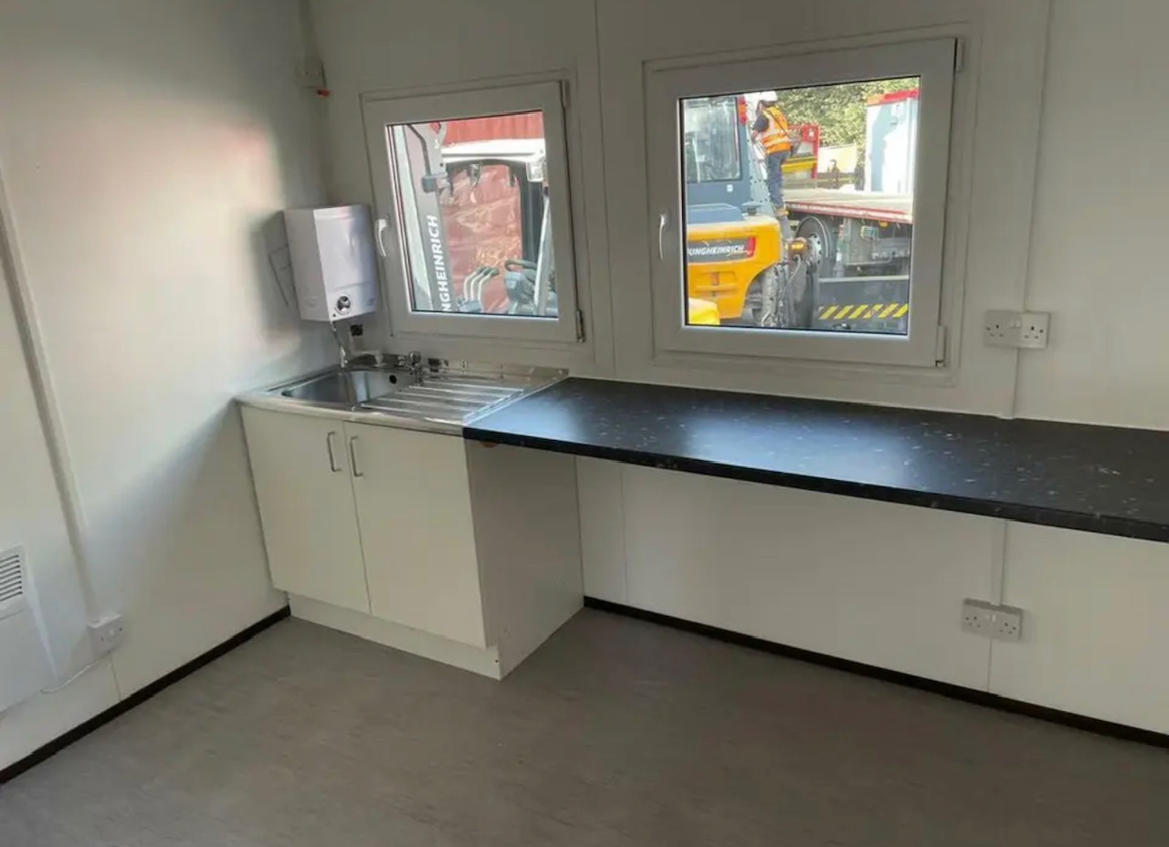
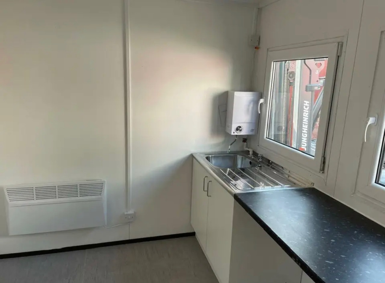
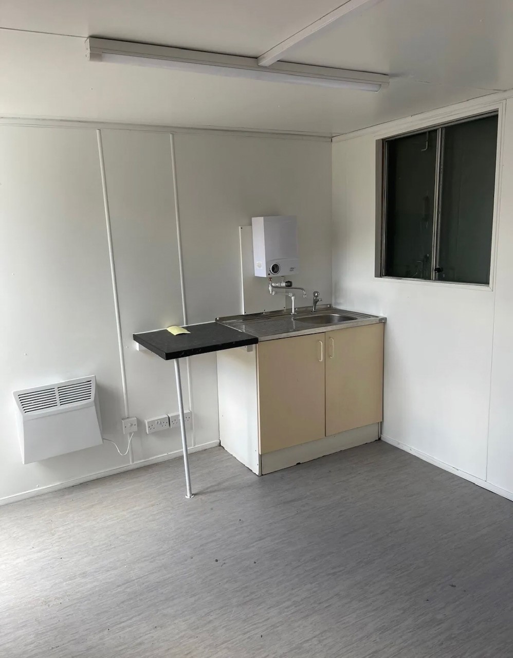
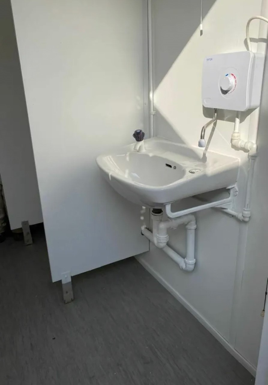
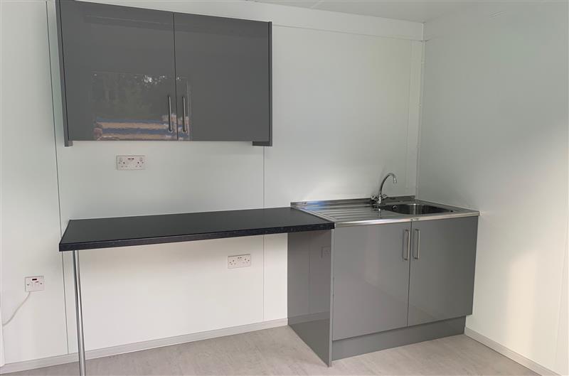
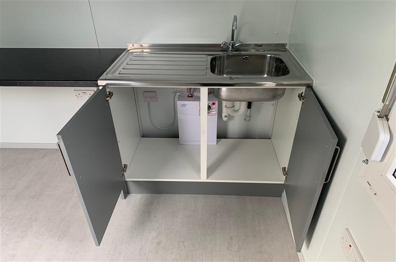
• Sink and water boiler included


Location: Nationwide
Quantity: ∞
EX VAT
Not Available for Hire
Call for an instant quote!


Location: Nationwide
EX VAT
Not Available for Hire
Call for an instant quote!
Get a Quick Container Quote Now!


Location: Nationwide
EX VAT
Not Available for Hire
Call for an instant quote!
Get a Quick Container Quote Now!